LightLas 532 – Operator's Manual Rev. No 01 Page 95 of 115
7.3 System Output Power Checking Procedure
This system output power checking procedures are intended to ensure the LightLas
532 system performance validation and it must be carried out by an authorized and
trained service agent. Therefore if you believe the Laser System is out of
specification or requires extended Calibration procedures you should have the
system checkout and verified by authorized and trained service prior to use the
equipment.
More detailed of these procedures are explained in the Service Repair Manual refer
to calibration section.
The procedure for checking the System Output Power is the same for the
Endoprobes, Slitlamp and LIO delivery units and the detailed procedures are listed
below:
Equipment Required:
- Power meter (Coherent Labmaster, Fieldmaster or Newport) CW 2W +/-
0.1W
- Safety glasses OD4+ / 532nm
Procedures:
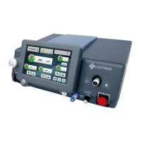
1. Ensure to plug the correct delivery key to the Laser Console as the front panel
indicator will show the correct unit is attached.
2. Set the remote controls panel setting to 50% duty cycle which the pulse interval
and pulse duration both set to 0.05 sec.
3. Set the system to Treat Mode and aim the output Aiming beam at the center of
the Power Meter detector with the spot size at around 5mm diameter or 50% of
the active detector area.
4. Set the Laser Power to levels of 100, 500, 1000 and 1500 mw and for each
setting fire the laser using the footswitch and note the External Power Meter
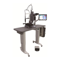
reading. For the Integrated Slitlamp Delivery the output power should be
checked at both the 200µ and 1000µ spot size settings and for the Attachment
Delivery Unit use the 100µ and 500µ spot sizes.
Note: For the Slitlamp Delivery units ensure that the Slitlamp Illumination tower is
pushed to one side so that it cannot block any of the Laser beams.
5. Ensure the reading multiply it by 2 (X2) to get the true power level as it is being
fired at 50% duty cycle. Record the X2 reading for each power setting on the
System Output Power Record Sheet.
6. Validate the measured power readings (X2) must be within +/-20% of the set
power for the system to be passed.