LightLas 532 – Operator's Manual Rev. No 01 Page 70 of 115
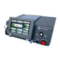
Laser Console
Prior to install the laser console device unit, ensure all the corrected setup and
equipment are in placed to proceed the installation steps.
Accessories:
Power cord (110 or 220 VAC type)
Delivery key (Slitlamp / LIO / Endoprobes)
Footswitch (wire or wireless)
Optical fiber (link from console aperture to the LDU could be Endoprobe
or standard delivery one)
Interconnector (Y-modified combination connector / treatment door
switch / default dummy connector)
On/Off Switch Key
Procedures:
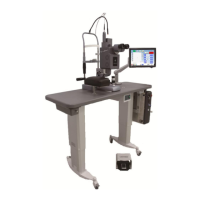
1. Position the laser console onto the mounting plate and to the right side of the
Slitlamp on the table top
2. Connect or fit all appropriate connectors (power cord, delivery key, interlock,
footswitch, key switch, and Endoprobe or standard delivery fiber)
2a. If this interlock is Y-modified connector, ensure the safety filter and YAG
interlock connections are well fitted (refer to fig. 5.21b)
3. Ensure all the connections are fitted no leftover since the improper connection or
no connection will result the system not functioning properly (refer to fig. 5.21a-c)
Note: Be extreme careful about the delivery fiber connection. The delivery fiber with
the large fiber holder end with delivery key attached is connected to the
console aperture and the another end is connected to appropriate delivery
system (refer to fig. 5.21c)
Take special care when preparing the fiber to not stress the cable. Hold the
connector when removing the protector caps from each end. Never pull on the
cable or the cable sleeve as the fiber may be damaged
 Loading...