LightLas 532 – Operator's Manual Rev. No 01 Page 79 of 115
Final Testing and Verification
11. Power on the console and ensure its delivery fiber is connected through the filber
holder (refer to fig. 5.24)
12. Configure the output power to 50mW, duration 0.2s, interval 0.2s, and spot size
50µ
13. Remove the target rod and place a thermal paper or black tape on the chinrest
14. Ensure the appropriate safety filter are attached accordingly (refer to fig. 5.23)
prior to trigger fire the laser shot
15. Fire the shot and verify if the burn pattern is visible if not also increase the power
16. Increase the spot size to 120µ and 200µ to see if the burn pattern is also getting
darker as the spot size increased
Note: At the higher power settings it may be possible to see a faint luminescence
glow at the target site when power setting is set at higher range furthermore this
transmission is under the Class I laser limitation.
As for other types of Attachment Slitlamp LDU such as, the Haag Streit style or Zeiss
30SL system, the alignment techniques are quite similar and the technique is to align
the Slitlamp focus and confirm it is at the same focal plane as the viewing optics.
Then align the Laser beams so that at the smallest spot size setting you can clearly
see that the Laser spot is at its smallest size at this focus plane. If this is OK then all
other spot sizes will match what is shown on the Spot size display.
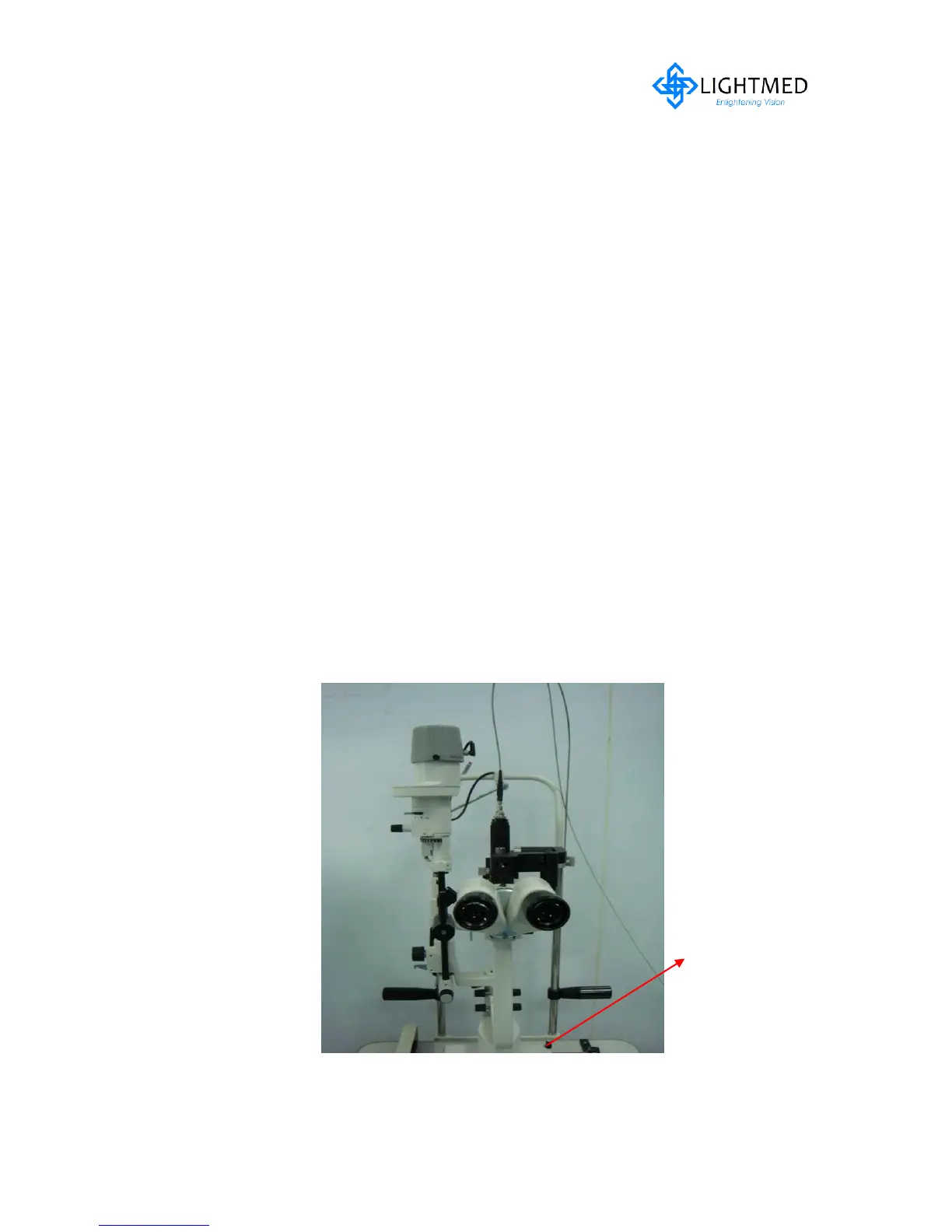
Figure 5.28(a) New Type Version
Check Slitlamp focus on Target Rod and Laser focus of aiming beam
Delivery Main Body
locking screw