Service Training
Section 2.6
Page 59
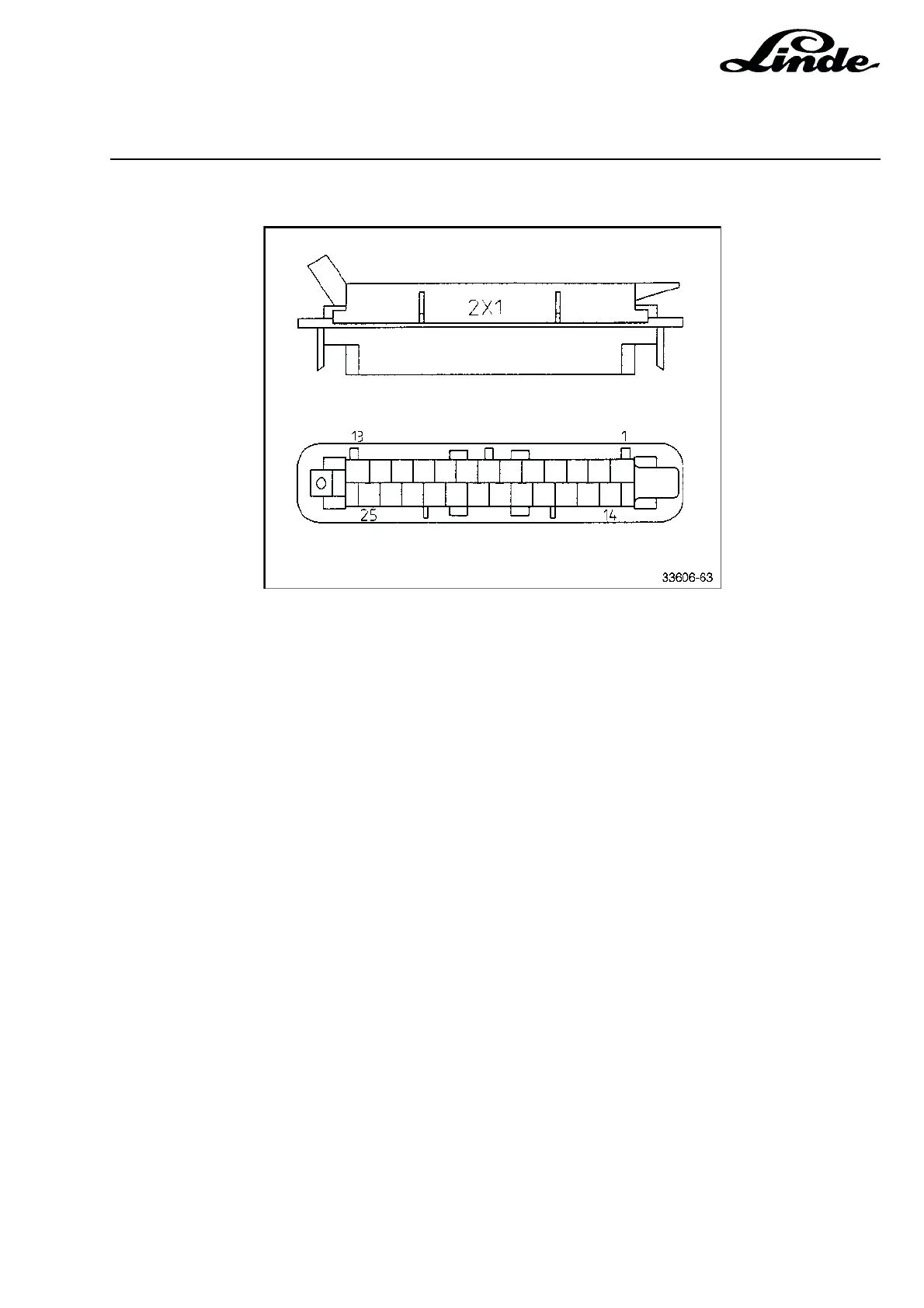
Pinout for connector 2X1
Terminal Colours Functions
1 not used
2 not used
3 not used
4 not used
5 not used
6 green/black power supply for sensors
7 not used
8 yellow/black +15 V power supply for sensors
9 blue/white thermal switch 2B6 for pump motor
10 brown enable signal from seat switch timer
11 white/yellow reed switch 3S1 signal steering control valve
12 not used
13 not used
14 white/red sensor 2B14 signal, auxiliary hydraulics 2
15 green/red sensor 2B13 signal, auxiliary hydraulics 1
16 violet sensor 2B12 signal, tilting
17 not used
18 green/blue discharge indicator cut-off contact
19 black/white sensor 2B11 signal, lifting
20 blue/red speed sensor 2B8 signal
21 not used
22 not used
23 not used
24 not used
25 red/black 24 V power supply
2.6.7.1 ELECTRONIC LIFT CONTROL