CHAPTER 4B CHASSIS ATV SERVICE MANUAL09.0
CHAPTER 4 CHASSIS PAGE. 4B-
4
NOTE: If reinstalling old brake shoes, install them
into their correct locations on the brake panel.
Refer to the “R U”, “L U”, “L U”, “L L” *marks made
in the Note of Disassembly.
*R-right, L-left, U-upper, L-lower
NOTE: If new linings are bring installed, file off the
leading edge of each shoe a little so that the brake
will not grab when applied.
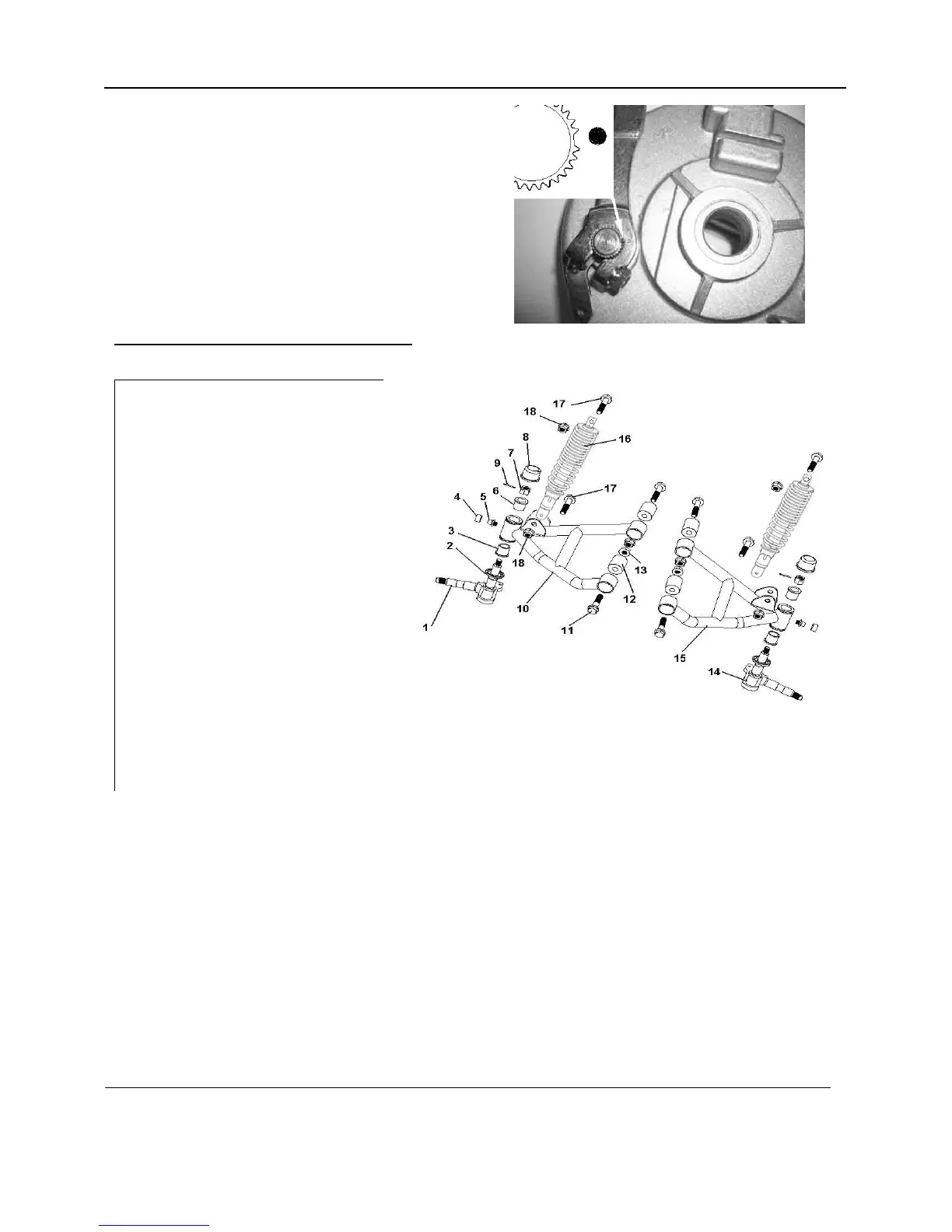
4.2. A-RM REPLACEMENT
1 A-ARM PIVOT SHAFT RIGHT
2 A-ARM PIVOT SHAFT SEALED RING
3 BUSHING 1
4 GREASE FITTING
5 GREASE FITTING CAP
6 BUSHING 2
7 NUT M10X1.25
8 A-ARM PIVOT SHAFT CAP
9 COTTER PIN2.5X20
10 A-ARM RITGHT
11 BOLT M10X1.25X48
12 A-ARM RUBBER BUSHING
13 CASTLE NUT M10X1.25
14 A-ARM PIVOT SHAFT LEFT
15 A-ARM LEFT
16 FRONT SHOCK ABSORBER
17 BOLT M10X1.25X38
18 NUT M10X1.25
REMOVAL
1. Remove wheel/ hub as described above.
2. Remove CAP (8), COTTER PIN (9), CASTLE NUT (13), and removal the PIVOT SHAFT
(14/ 1).
3. Remove BOLTS (17) and removal FRONT SHOCK ABSORBER.
4. Remove 4 bolts (11) and removal A-ARM.
INSPECTION
Clean and Inspect the bushing 1, bushing 2, A-ARM RUBBER BUSHING, FRONT SHOCK
RUBBER BUSHING and the PIVOT SHAFT for nicks, scratches, or damage. Replace if
necessary.
 Loading...