CHAPTER 5 FINAL DRIVE ATV SERVICE MANUAL 09.0
CHAPTER 5 FINAL DRIVE. 5-
2
5.1 WH E E L , H U B , AND SPINDLE TORQUE TABLE
Item Specification
ATV26./300/B Type:20 Ft.Lbs 27 N.m Front Wheel Nuts
ATV400:48 Ft.Lbs 66 N.m
ATV26./300/B Type:50 Ft.Lbs 69 N.m Rear Wheel Nuts
ATV400:48 Ft.Lbs 66 N.m
Front Hub Nut on Spindle/ outer CV joint Refer to FRONT HUB INSTALLATION
pe:80 Ft.Lbs 110.6 N.mRear Hub Retaining Nut
ATV400:101Ft.Lbs 137N.m
CAUTION: Locking nuts, and bolts with pre-applied locking agent should be replaced if
removed. The self- locking properties of the nut or bolt are reduced or destroyed during removal.
5.2 FRONT HUB DISASSEMBLY/INSPECTION
1. Elevate front end and safely support
machine under footrest/frame area.
CAUTION
Serious injury may result if machine tips
or falls. Be sure machine is secure
before beginning this service procedure.
Wear eye protection when removing
bearings and seals.
2. Check bearings for side play by grasping
tire/wheel firmly and checking for
movement. It should rotate smoothly
without binding or rough spots.
3. Remove wheel nuts and wheel.
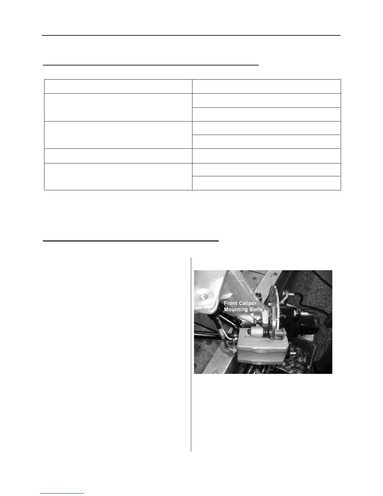
4. Remove brake caliper
5.
Remove hub cap, cotter pin, front
spindle nut, and washer.
6. Rotate each bearing by hand and check for
smooth rotation. Visually inspect bearing
for moisture, dirt, or corrosion. Replace
bearing
if moisture, dirt, corrosion, or
 Loading...