4 Installation
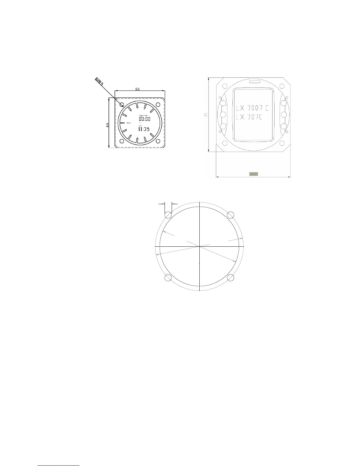
4.1 Mechanical layout
Vario Main unit
Main unit installation template
4.2 Installation of main unit
Prepare the cut-out in the instrument panel According to the drilling template.
Remove the press-in covers from the four main selectors on the LX 7007 PRO IGC.
You can now see the mounting screws. While holding the knobs, slacken the screws with
a screwdriver. Now the knobs can be removed (never use power to remove the knobs,
you can damage rotary switches). By problems hit on the slacken screw a little bit.
Remove the four special type screws. Position the LX 7007 PRO IGC in the cut-out in the
instrument panel. Tighten the LX 7007 PRO IGC with the special screws (8 mm tool).
Tighten the knobs and replace the covers LX 7007 vario don’t need any changes having standard 57 mm cut-
out.