Lynx
®
NGT-9000
Pilot’s Guide2-2
Operation
POWER (PANEL MOUNT)
There is no power on/off switch on the panel mount version of the Lynx
NGT-9000. Depending on the aircraft, use either the battery switches
or avionics master switch to apply power. After power is applied the
unit begins initialization and self-tests begin. When on ground the unit
cycles through the following screen sequence:
Splash
System Status / Version
Flight ID (optional)
Normal Operation
When in air and power is cycled the unit transitions to normal
operation within 5 seconds, bypassing the splash, version and flight
ID screens.
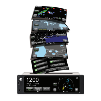
Splash Screen
The splash screen is displayed in less than 5 seconds after power is
applied. The company name/Logo is shown on the left side and the
product name on the right. See Figure 2-1.
•
•
•
•
Figure 2-1: Example of Splash Screen
NORMAL OPERATION (REMOTE MOUNT)
Operational control of the remote mount version of the Lynx NGT-
9000 is accomplished with a CP-2500 Control Panel. An ADS-B Out
Fail lamp (if installed) can provide system status.
Operation and control information for the CP-2500 Control Panel is
found in Chapter 3 (Controls and Indicators) or in the CP-2500 Pilot’s
Guide (0040-17250-01).
 Loading...