© 2019 EnergyLogic, LLC Toll Free: 800 311 8828 Fax: 615 471 5202 www.energylogic.com 58
Rev. Date 040819
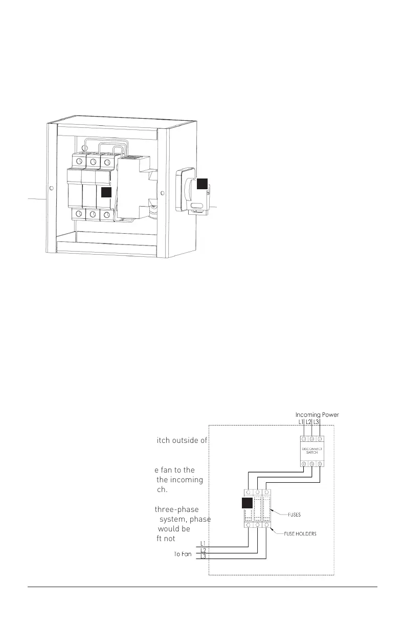
6.1 Fuse Disconnect Switch
Installation (Recommended but
optional)
A
B
The fuse disconnect switch is an optional
component offered by EnergyLogic. Reference
page 5 for fuse size based upon the incoming
power and fan diameter.
6.1.1: Mount the fuse disconnect switch outside of
the swept area of the fan airfoils.
6.1.2: Wire the power cable from the fan to the
bottom of the fuse block. Then wire the incoming
power source to the disconnect switch.
6.1.3: In the diagram to the right, a three-phase
system is shown. For a single phase system, phase
1 would be connected to L1, neutral would be
connected to L2, and L3 would be left not
terminated.
C
Components:
A - Fuse Block (Optional Add-On)
B - Disconnect Switch (Optional Add-On)
C - Class gG Fast Acting Fuses (Not Provided) - refer to the fuse chart on page 5
NOTE: Ensure that there is no power when installing this component.
Means for disconnection with contact separation at least 3mm.
Service Disconnect (Required
per NEC, OSHA, IEC, CE and
UL compliance).
Not Included -
Optional Add-On