© 2019 EnergyLogic, LLC Toll Free: 800 311 8828 Fax: 615 471 5202 www.energylogic.com 8
Rev. Date 040819
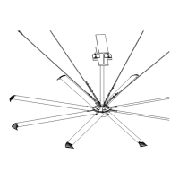
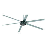
Fan Placement & Clearance
WARNING: FANS ARE NOT MEANT TO BE OPERATED IN WINDY CONDITIONS.
The Fixed Angle Mount should only be used if the mounting surface is not a compound angle
(sloping in multiple directions). The Universal Mount should be used for all compound angle
surfaces.
Maximum Fixed Angle for Mount (feet)
Slope (in) 0 2/12 4/12 6/12 8/12 10/12
Roof Angle 0 9.5
o
18.4
o
26.6
o
33.7
o
39.8
o
Diameter Recommended Total Drop (Mount to Airfoil) Length (ft)
10 feet 3 3 3 4 5 6
12 feet 3 3 3 5 6 7
14 feet 3 3 4 5 7 8
16 feet 3 3 4 6 7 9
18 feet 3 3 5 7 8 N/A*
20 feet 3 4 5 7 9 N/A*
24 feet 3 4 7 9 N/A* N/A*
*Need Universal Mount with Guy wires
The drop lengths above are minimum recommendations only, based solely on roof pitch and fan
diameter. Other factors, such as allowing for proper airow into the fan must be evaluated when
determining drop length requirements. In addition, EnergyLogic strongly recommends that the
fan airfoils must be a minimum of 10 feet (3.05 meters) above the oor. Contact EnergyLogic for
assistance with fan placement and drop length selection (contact information can be found on
page 74).
The table below shows the clearance
needed from the fan to obstructions such
as lighting, conduit, etc.
Minimum Clearance (Horizontal / Vertical inches):
Airfoil / Drop Length (ft) 2 3 4 5 6 7 8 9 10
10 feet 7 / 7 7 / 7 7 / 7 7 / 8 8 / 8 9 / 9 10 / 9 12 / 10 13 / 11
12 feet 7 / 8 7 / 8 7 / 9 7 / 9 8 / 9 9 / 10 10 / 11 11 / 12 13 / 12
14 feet 7 / 9 7 / 9 7 / 10 7 / 10 8 / 11 9 / 11 10 / 12 11 / 13 13 / 14
16 feet 7 / 10 7 / 10 7 / 11 7 / 11 8 / 12 9 / 13 10 / 14 11 / 15 13 / 16
18 feet 7 / 12 7 / 12 7 / 12 7 / 13 8 / 14 9 / 15 10 / 16 11 / 17 13 / 18
20 feet 7 / 14 7 / 14 7 / 14 7 / 15 8 / 16 9 / 17 10 / 18 11 / 19 13 / 21
24 feet 7 / 19 7 / 19 7 / 20 7 / 20 8 / 21 9 / 22 10 / 24 11 / 25 13 / 27