16
57-606 ECLIPSE Model 706 Guided Wave Radar Transmitter
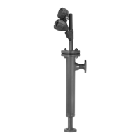
2.4.3 Installing a Caged Probe
Models 7yG, 7yL and 7yJ
Before installing, ensure that the:
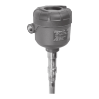
• The model and serial numbers shown on the nameplates of
the ECLIPSE probe and transmitter are identical. For opti-
mal performance (and correlation to the Calibration
Certificate included with all units), transmitters and probes
should be installed as a matched set.
• Probe has adequate room for installation and has unob-
structed entry to the bottom of the vessel.
• Process temperature, pressure, dielectric, and viscosity are
within the probe specifications for the installation. See
Specifications, Section 3.6.
NOTES: Model 7yL and 7yJ probes (High Pressure/High Temperature
probes (containing a glass ceramic alloy process seal) should
be handled with extra care. Only handle these probes by the
flanges or NPT connection. Do not lift probes by the shaft.
If using a segmented caged probe, ensure that all pieces are
assembled and connected before installation.
2.4.3.1 To install a caged probe:
1. Ensure that the process connection is the correct flanged
mounting.
2. Carefully place the probe into the vessel. Properly align the
gasket on flanged installations.
NOTE: A metallic gasket must be used to ensure an adequate
electrical connection between the probe flange and the cage
(chamber). This connection is critical to obtain true overfill
performance.
3. Align the probe process connection flanged mounting on
the cage.
4. Tighten flange bolts.
NOTES: If the transmitter is to be installed at a later time, do not remove
the protective cap from the probe.
Do not use sealing compound or TFE tape on probe connec-
tion to transmitter as this connection is sealed by a Viton
®
o-ring.