17
57-606 ECLIPSE Model 706 Guided Wave Radar Transmitter
2.4.4 Installing a Single Rod Probe
Rigid Models 7yF, 7yG, 7yJ, 7yL, 7yM and 7yN
F
lexible Models 7y1, 7y2, 7y3 and 7y6
Before installing, ensure that the:
• The model and serial numbers shown on the nameplates of
the ECLIPSE probe and transmitter are identical. For opti-
mal performance (and correlation to the Calibration
Certificate included with all units), transmitters and probes
should be installed as a matched set.
• Probe has adequate room for installation and has unob-
structed entry to the bottom of the vessel.
• Process temperature, pressure, dielectric, and viscosity are
within the probe specifications for the installation. See
Specifications, Section 3.6.
For standard Non-Overfill-Capable Single Rod probes
installed directly into a vessel:
NOTE: If using a removable rod, ensure that all pieces are assembled
and connected before installation.
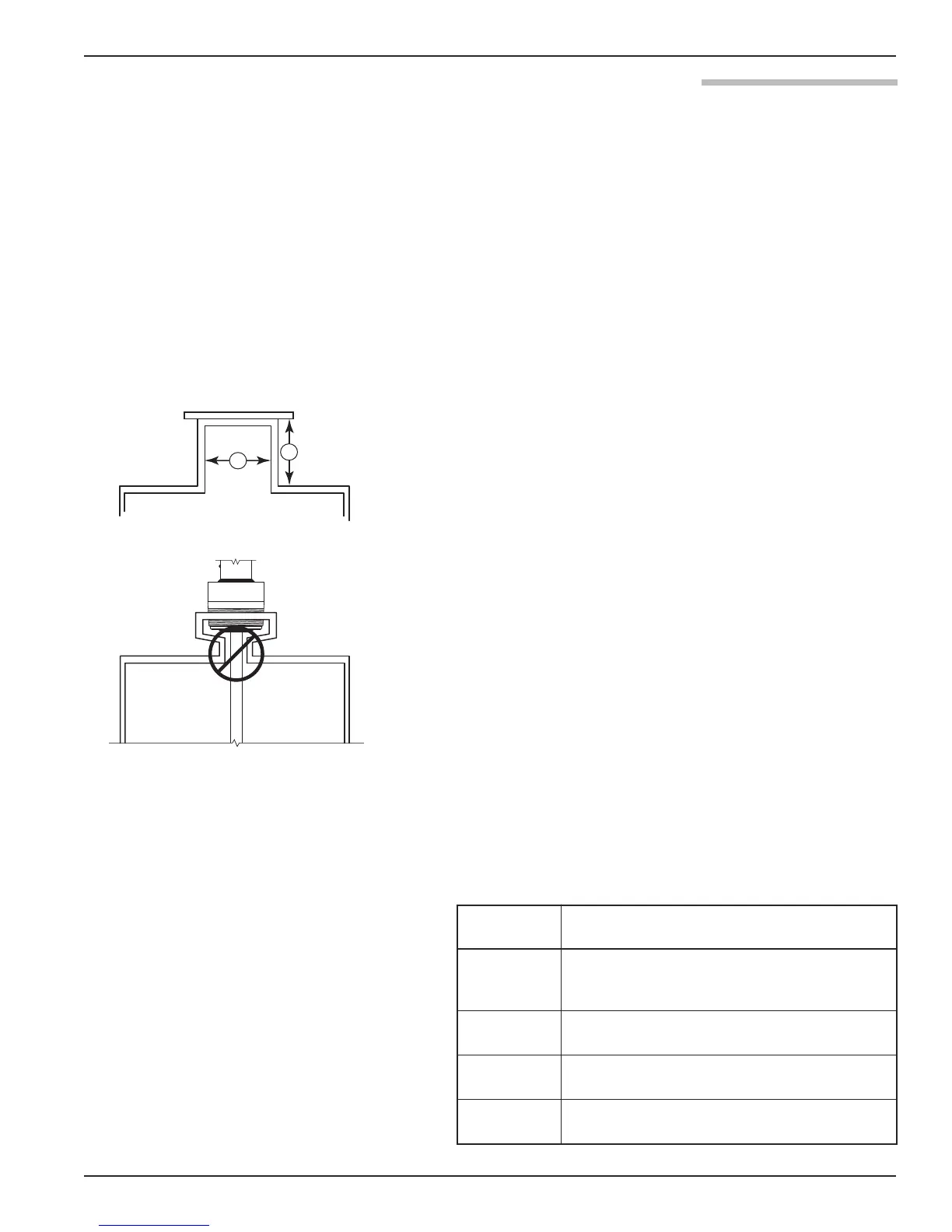
1. Ensure that the nozzle does not restrict performance by
ensuring the following:
• Nozzle is > 2" (50mm) diameter.
• Ratio of Diameter: Length (A:B) is 1:1 or greater; any ratio
<1:1 (e.g., a 2"¥ 6" nozzle = 1:3) may require a Blocking
Distance and/or DIELECTRIC RANGE adjustment.
2. No pipe reducers (restrictions) are used.
3. Probe is kept away from conductive objects to ensure proper
performance.
• See Probe Clearance Table below. A lower gain (increase in
DIELECTRIC RANGE setting) may be necessary to ignore
certain objects
• This table is only a recommendation. These distances can
be improved by optimizing the transmitter configuration
with PACTware
™
.
Distance
to Probe
Acceptable Objects
<6" (15 cm)
Continuous, smooth, parallel conductive sur-
face, for example a metal tank wall; important
that probe does not touch wall
>6" (15 cm)
<1" (25 mm) diameter pipe and beams,
ladder rungs
>12" (30 cm)
<3" (75 mm) diameter pipe and beams,
concrete walls
>18" (46 cm) All remaining objects