27
57-606 ECLIPSE Model 706 Guided Wave Radar Transmitter
N
OTE: Current measurements taken at these test points are an
approximate value. Accurate current readings should be
taken with the digital multimeter directly in series with the
loop.
NOTE: When using a HART communicator for configuration, a mini-
m
um 250-ohm line load resistance is required. Refer to your
HART communicator manual for additional information.
NOTE: The transmitter can be configured without the probe.
Disregard the “No Probe” diagnostic indicator that will appear.
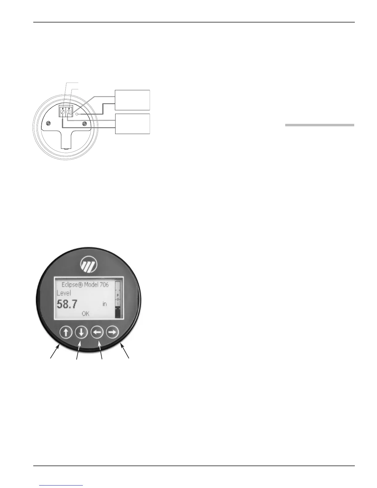
2.6.2 Menu Traversal and Data Entry
The four push buttons offer various forms of functionality
for navigation and data entry.
The Model 706 user interface is hierarchical in nature,
best described as a tree structure. Each level in the tree
contains one or more items. Items are either menu labels
or parameter names.
• Menu labels are presented in all capital letters
• Parameters are capital words
2.6.2.1 Navigating the Menu
UP moves to the previous item in the menu branch.
DOWN moves to the next item in the menu branch.
BACK moves back one level to the previous (higher)
branch item.
ENTER enters into the lower level branch or switches
to the entry mode. Holding the ENTER down on any
highlighted menu name or parameter will show help
text for that item.
2.6.2.2 Data Selection
This method is used for selecting configuration data from
a specific list.
UP and DOWN to navigate the menu and high-
light the item of interest.
ENTER allows modification of that selection.
UP and DOWN to choose new data selection.
ENTER to confirm selection.
Use BACK (Escape) key at any time to abort the pro-
cedure and escape to previous branch item.
➪
➪
➪
➪
➪
➪
➪
➪
➪
➪
➪
Up Down Back Enter
+
–
+
–
Power Supply
2
4 VDC
(-) negative
(+) positive
T
est
Current Meter
G.P./I.S./Explosion Proof Model