70
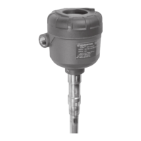
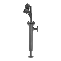
57-606 ECLIPSE Model 706 Guided Wave Radar Transmitter
3.6 Specifications
3.6.1 Functional/Physical
System Design
Measurement Principle Guided Wave Radar based on Time Domain Reflectometry (TDR)
Input
Measured Variable Level, as determined by GWR time of flight
Span 6 inches to 100 feet (15 cm to 30 m); Model 7yS Probe 20 feet (610 cm) max.
Output
Type 4 to 20 mA with HART: 3.8 mA to 20.5 mA useable (per NAMUR NE43)
F
OUNDATION
™
fieldbus: H1 (ITK Ver. 6.1.1)
Modbus RS-485
Resolution Analog: .003 mA
Digital Display: 1 mm
Loop Resistance 591 -ohms @ 24 VDC and 22 mA
Diagnostic Alarm Selectable: 3.6 mA, 22 mA (meets requirements of NAMUR NE 43), or HOLD last output
Damping Adjustable 0–10 seconds
User Interface
Keypad 4-button menu-driven data entry
Display Graphic Liquid Crystal Display
Digital Communication HART Version 7—with Field Communicator, F
OUNDATION fieldbus
™,
AMS, or FDT
DTM (PACTware
™
), EDDL
Menu Languages Transmitter LCD: English, French, German, Spanish, Russian
HART DD: English, French, German, Spanish, Russian, Chinese, Portuguese
F
OUNDATION fieldbus and Modbus Host Systems: English
Power (at transmitter terminals) HART: General Purpose (Weather proof)/Intrinsically Safe/Explosion-proof:
11 VDC minimum under certain conditions (refer to Section 3.6.11)
F
OUNDATION fieldbus
™
: 9 to 17.5 VDC
FISCO FNICO, Explosion Proof, General Purpose and Weatherproof
Modbus: 8 to 30 VDC
Explosion Proof, General Purpose, and Weatherproof
Housing
Material IP67/die cast aluminum A413 (<0.4% copper); optional stainless steel
Net/Gross Weight Aluminum: 4.5 lbs. (2.0 kg)
Stainless Steel: 10.0 lbs. (4.50 kg)
Overall Dimensions H 8.34" (212 mm) x W 4.03" (102 mm) x D 7.56" (192 mm)
Cable Entry
1
⁄2" NPT or M20
SIL 2 Certification (Safety Integrity Level) Safe Failure Fraction = 93% (HART only)
Functional Safety to SIL 2 as 1oo1 in accordance with IEC 61508
(Full FMEDA report available upon request)