MAN B&W 5.18
Page 6 of 8
MAN Diesel
198 53 221.5MAN B&W 70-26 engines
20- 0ITCH
#OORDINATED
#ONTROL
3YSTEM
(ANDLES
INTERFACE
$UPLICATEDæ.ETWORK
%NGINE
SAFETY
SYSTEM
%NGINEæSPEED
3YSTEMæFAILUREæALARMæ,OADæREDUCTIONæ,OADæREDæ#ANCELæALARM
%NGINEæOVERLOADæMAXæLOAD
34/0
'OVERNORæLIMITERæCANCEL
20- 0ITCH
)
3TART3TOP3LOWæTURNINGæ3TARTæBLOCKINGæ2EMOTE,OCAL
!HEAD
!STERN
2EMOTE,OCAL
&UELæ)NDEX
#HARGEæ!IRæ0RESS
4ERMINALSæFOR
PROPELLER
MONITORING
SENSORS
0
)
0ITCH
0ITCHæ3ET
,OCALæENGINEæ
CONTROL
3PEEDæ3ET
0ROPULSION
#ONTROL
3YSTEM
"RIDGEæ7ING
3HUTæDOWNæ3HUTæDOWNæRESETCANCEL
0ROPELLERæ0ITCH
#LOSEDæ,OOP
#ONTROLæ"OX
0ITCH
/PERATOR
0ANELæ
/PERATOR
0ANEL
/PERATOR
0ANEL
"ACKUPæSELECTED
3HAFTæ'ENERATOR
æ0-3
!UXILIARYæ#ONTROL
%QUIPMENT
3HIPS
!LARM
3YSTEM
%3
-AINæ#ONTROLæ3TATION
#ENTER
"RIDGEæ7ING
"5æ"ACK5Pæ#ONTROL
"RIDGE
%NGINEæ#ONTROLæ2OOM
%NGINEæ2OOM
34/0
0
)
0
)
34!24
/PERATOR
0ANELæ
20- 0ITCH 20- 0ITCH
%3æ%MERGENCYæ3TOP
%3 "5 %3
/PERATOR
0ANEL
/0ç0
4ERMINALSæFOR
ENGINEæMONITORING
SENSORS
34/0
)NæGOVERNOR
'OVERNOR
/6%2
,/!$
178 22 406.1
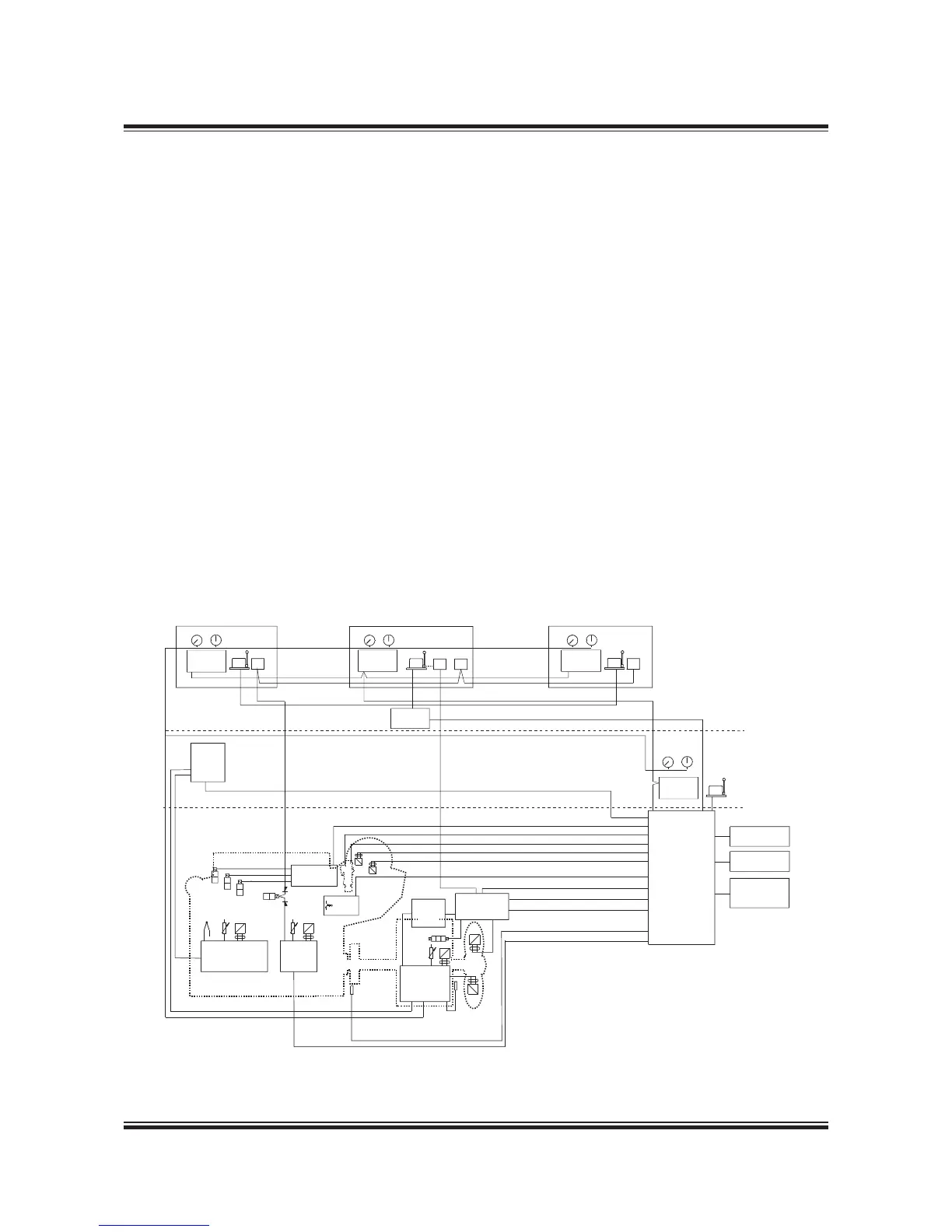
Fig. 5.18.07: MAN Alphatronic 2000 Propulsion Control System
MAN Alphatronic 2000 Propulsion Control
System
MAN Diesel & Turbo’s MAN Alphatronic 2000 Pro-
pulsion Control System (PCS) is designed for con-
trol of propulsion plants based on diesel engines
with CP propellers. The plant could for instance
include tunnel gear with PTO/PTI, PTO gear, mul-
tiple engines on one gearbox as well as multiple
propeller plants.
As shown in Fig. 5.18.07, the propulsion control
system comprises a computer controlled system
with interconnections between control stations via
a redundant bus and a hard wired backup control
system for direct pitch control at constant shaft
speed.
The computer controlled system contains func-
tions for:
• Machinery control of engine start/stop, engine
load limits and possible gear clutches.
• Thrust control with optimization of propeller
pitch and shaft speed. Selection of combina-
tor, constant speed or separate thrust mode is
possible. The rates of changes are controlled to
ensure smooth manoeuvres and avoidance of
propeller cavitation.
• A Load control function protects the engine
against overload. The load control function con-
tains a scavenge air smoke limiter, a load pro-
gramme for avoidance of high thermal stresses
in the engine, an automatic load reduction and
an engineer controlled limitation of maximum
load.
• Functions for transfer of responsibility be-
tween the local control stand, engine control
room and control locations on the bridge are
incorporated in the system.
 Loading...