MAN B&W 15.06
Page 1 of 2
MAN Diesel
198 49 11-1.4MAN B&W S65ME-C8/-GI
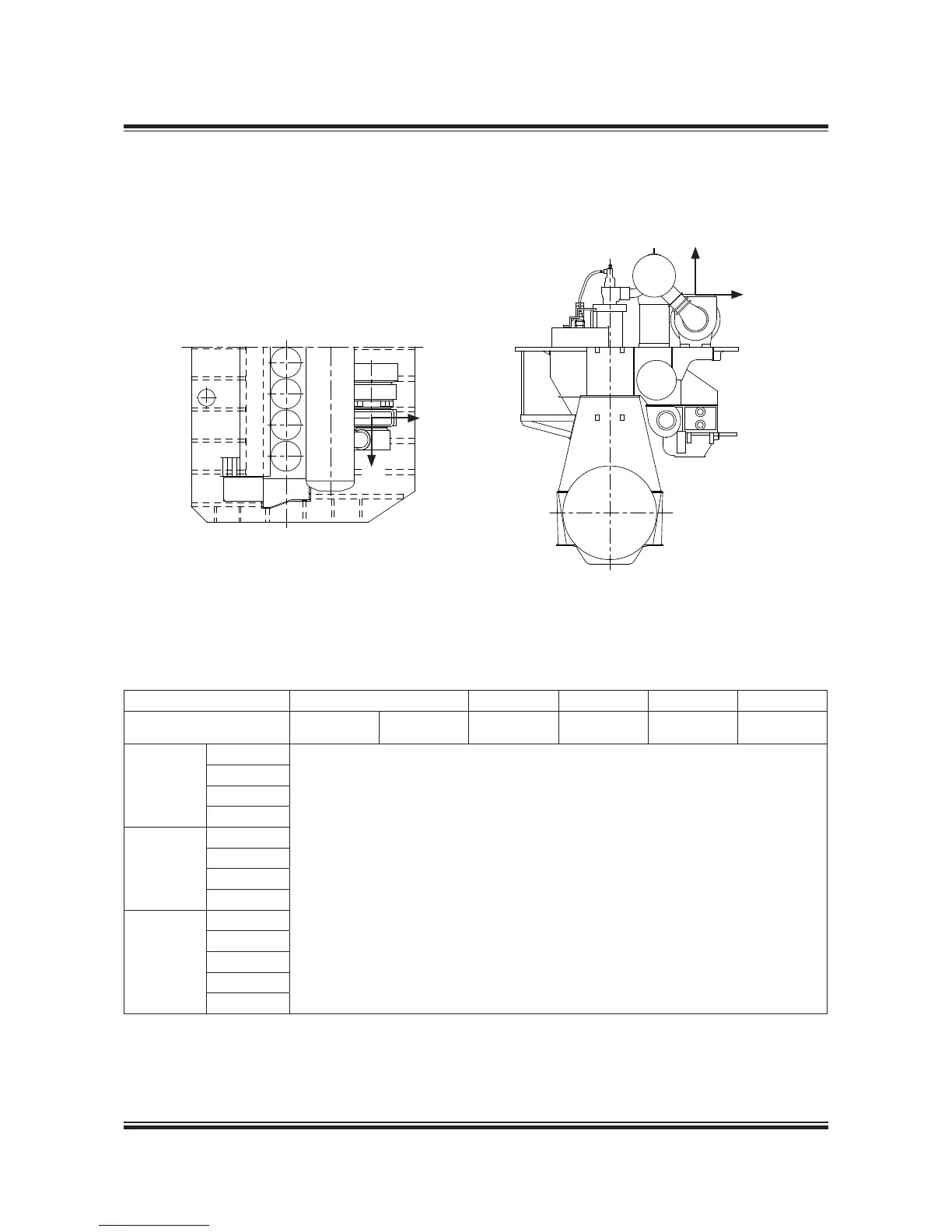
Forces and Moments at Turbocharger
$!
$"
$"
$#
Fig. 15.06.01: Vectors of thermal expansion at the turbocharger exhaust gas outlet flange
078 87 11-1.0.0b
Table 15.06.02: Max. expected movements of the exhaust gas flange resulting from thermal expansion
No. of cylinders 5-8 5678
Turbocharger DA DB DC DC DC DC
Make Type mm mm mm mm mm mm
MAN
TCA55
Available on request
TCA66
TCA77
TCA88
ABB
A275
A180 / A280
A185 / A285
A190
MHI
MET53
MET60
MET66
MET71
MET83
DA: Max. movement of the turbocharger flange in the vertical direction
DB: Max. movement of the turbocharger flange in the transversal direction
DC: Max. movement of the turbocharger flange in the longitudinal direction
Data for more turbocharger makes and types for the S65ME-C8/-GI engines are available on request.
 Loading...