MAN B&W 16.02
Page 2 of 6
MAN Diesel
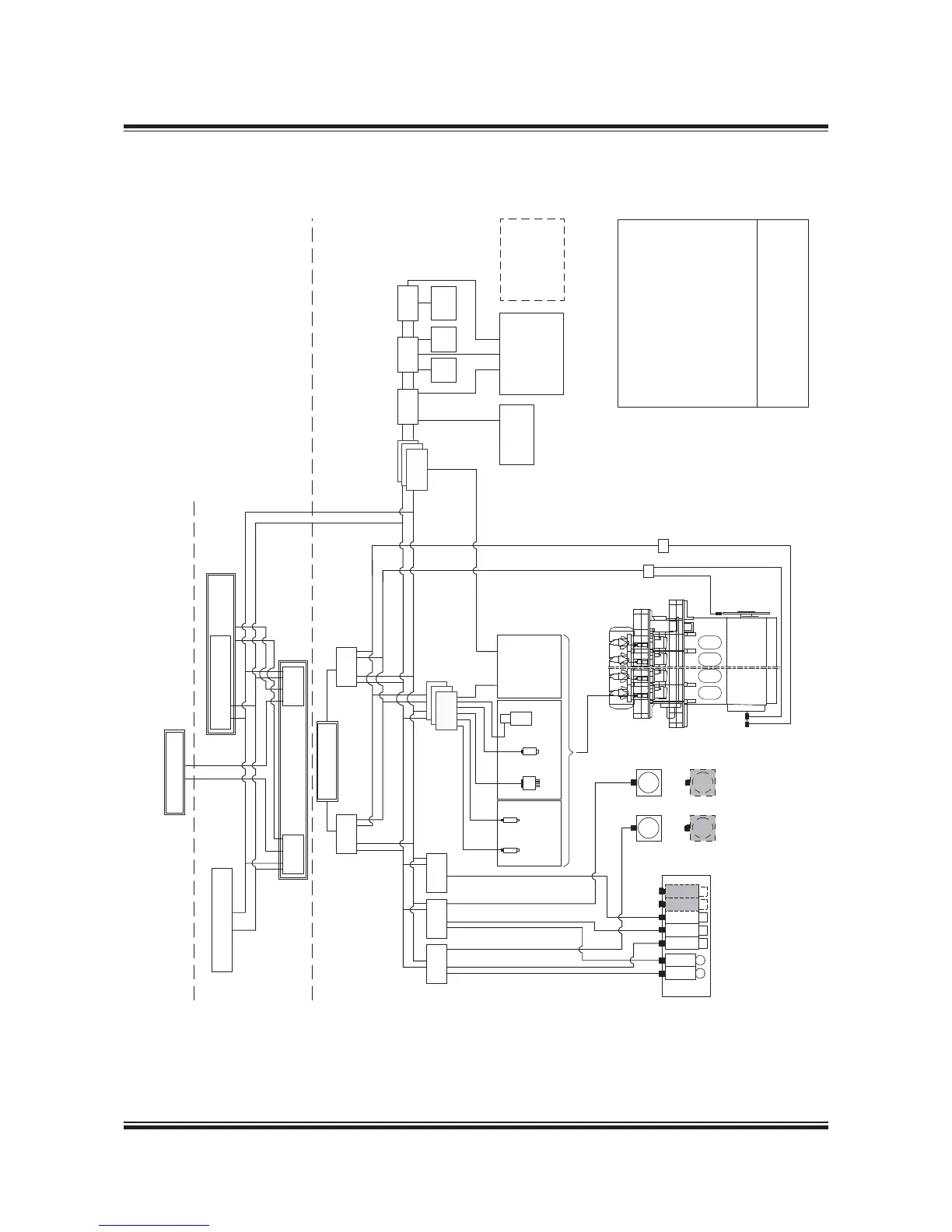
MAN B&W ME-GI engines 198 89 31-2.1
GI ExtensionME-ECS
ALS
Actuators
SAV
Cylinder 1
FIVA
Valve
Sensors
Fuel
booster
position
Exhaust
valve
position
On Bridge
In Engine Control Room
On Engine
ECU A
EICU A EICU B
ECU B
Backup Operation Panel
MOP B
Bridge Panel
Local Operation
Panel - LOP
Auxiliary
Blower 2
Auxiliary
Blower 1
Auxiliary
Blower 4
Auxiliary
Blower 3
ECR Panel
ACU 1 ACU 3ACU 2
Main Operation Panel
MOP A
Angle
Encoders
Marker
Sensor
M
M
M
M
M
Pump 1
M
M
Pump 2
Pump 1
Pump 2
Pump 3
Pump 5
Cabinet for EICU
ELGI ELWI
Gas press.
Purge valves
Blow-off valves
Cylinder 1
Gas supply system
Gas return system *)
ACU - Auxiliary Control Unit
ALS - Alpha Cylinder Lubrication System
CCU - Cylinder Control Unit
ECU - Engine Control Unit
EICU - Engine Interface Control Unit
ELGI - Electronic Gas Injection
ELWI - Electronic W
FIVA - Fuel Injection Valve Actuation
HPS - Hydraulic Power Supply
LOP - Local Operation Panel
MOP - Main Operation Panel
SAV - Starting Air Valve
GACU - Gas Auxiliary Control Unit
GCSU - Gas Cylinder Safety Unit
GPCU - Gas Plant Control Unit
GPSU - Gas Plant Safety Unit
ME
GI
*) Option
Pump 4
GPCU GACU
Inert
gas
Vent.
air
Sealing
oil
GPSU
Safety system
Cylinder 1
HPS
CCU
Cylinder 1
GCSU
178 53 035.3
Fig. 16.02.01: MEGI Engine Control System
 Loading...