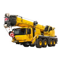
Driving with rigged crane
8.6 Tables with boom positions and axle loads
Lattice extension operating instructions 3 112 441 en 8 - 5
GMK 4100/4100-L/5095
11.01.2008
8.6 Tables with boom positions and axle loads
Notes on
the tables
The axle loads specified in the following tables:
– Refer to a driving mode with the basic unit
– Apply both to the derricking swing-away lattice as well as to the inclinable
swing-away lattice
H
The maximum axle load specified in the table is reached at a main boom
angle of either 0° or 45°. When the maximum axle load is reached e.g. at the
front, the axle load at the rear is below the specified maximum axle load.
At main boom angles between 0° and 45°, the axle loads are below the spec-
ified maximum axle loads.
The following applies to the foot notes in the tables:
1)
Boom position at the rear: 0° position, boom over rear edge of
truck crane
Boom position at the front: 180° position, boom over driver's cab
2)
Front axle load: On both the first and second axle line
Rear axle load: On both the third and fourth axle line
 Loading...


