Boom extension
4.2 Description of the rigging work
4 - 12 3 112 441 en Lattice extension operating instructions
GMK 4100/4100-L/5095
11.01.2008
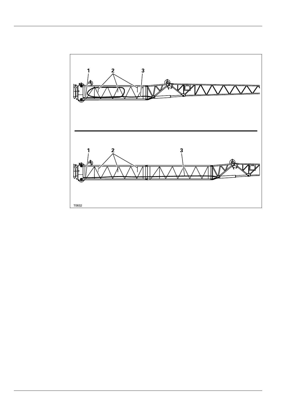
4.2.3 Hydraulic connection at the boom extension
H
This section only applies to the hydraulically derricking lattice extension.
The hoses are attached in section 3 in such a way that short ends (1) pro-
trude out of section 3 at the rear and long ends (3) at the front.
With the 22 m (72 ft) boom extension, the long ends (3) are attached to the
holders (2).
If the 27 m (89 ft) boom extension is rigged, the long ends (3) are laid
through section 4. The holders (2) are not used.
The short ends (1) of the hoses are at the rear on the lower cross-strut.
The allocation of the quick release couplings is determined by the shapes
and sizes.
27 m (89 ft) boom extension
22 m (72 ft) boom extension
 Loading...