BOOM GRT8100 SERVICE MANUAL
4-24
Published 3/26/2018, Control # 596-05
52. Remove wear pad assembly (78) from front of tele 2 (3)
(left and right sides) (see Figure 4-23).
53. Slightly lower tele 3 (4).
54. Remove four bolts (13) and flat washers (10) securing
keeper plate (77) to front of tele 2 (3) (left, right, and
center) (see Figure 4-23).
55. Remove two bolts (18) securing stop block (14) and
shim (15) to front of tele 2 (3) (left and right sides) (see
Figure 4-23).
56. Remove wear pad (76) and two shims (75) from front of
tele 2 (3) (see Figure 4-23).
57. Remove tele 3 (4) from tele 2 (3). Set tele 3 (4) on
adequate supports.
58. Remove wear pad (126) and shim (124) from rear of tele
3 (4) (left and right sides) (see Figure 4-24).
59. Detach grease hose assembly (66, 69, 70) from wear
pad (125) at rear of tele 3 (4) (left and right sides) (see
Figure 4-24).
60. Remove two capscrews (56) securing wear pad (2x-53)
and wear pad (4x-54) to rear of tele 3 (4) (see
Figure 4-24).
61. Remove two capscrews (31), lock washers (28), and flat
washers (27) securing wear pad (122) to rear of tele 3
(4) (see Figure 4-25).
62. Remove two capscrews (85) and flat washers (91)
securing shaft (115) in position at rear of tele 3 (4).
Remove roller (90), shaft (115), and five narrow washers
(116) from rear of tele 3 (4) (see Figure 4-26 and
Figure 4-27).
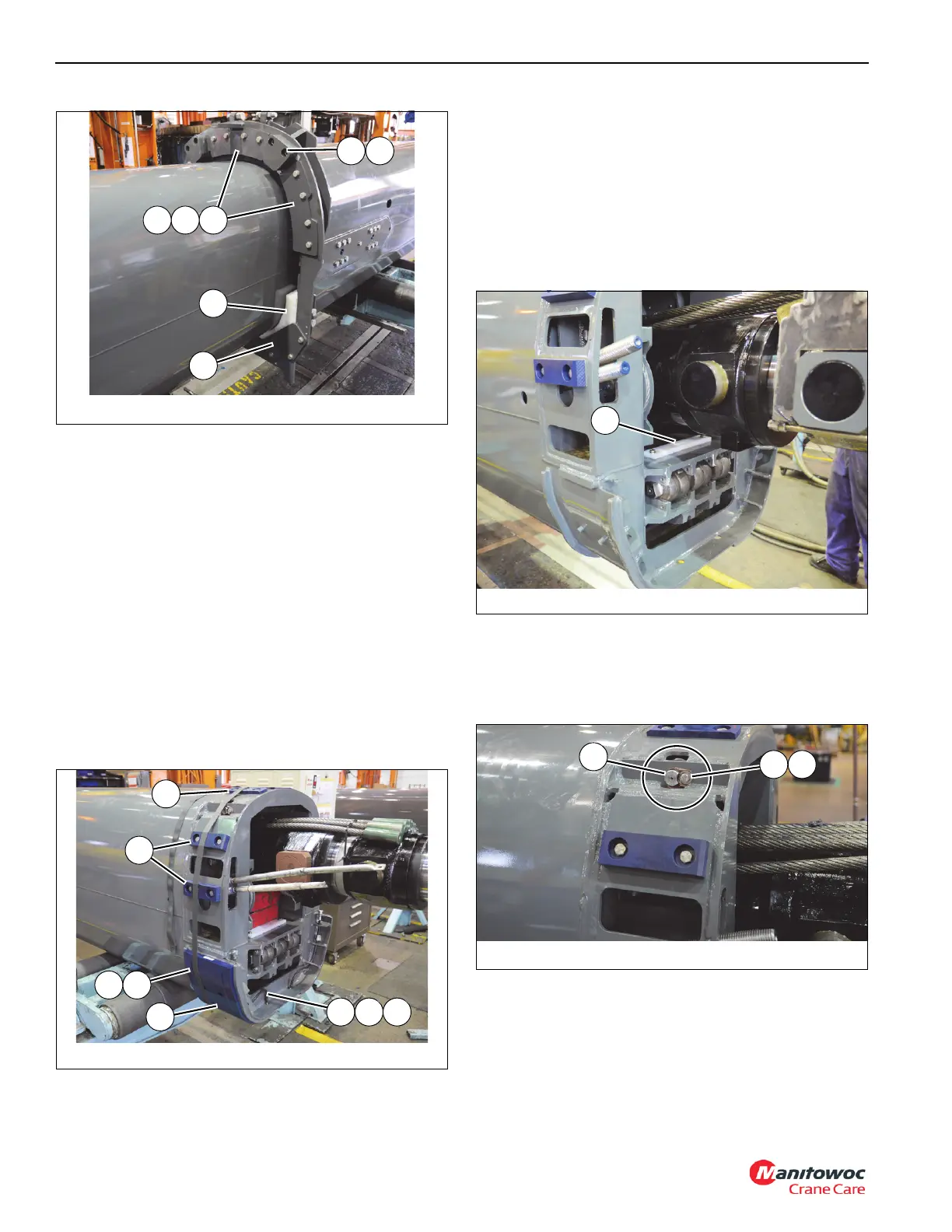
FIGURE 4-23
8804-56
20
78
77
14 15
7675
FIGURE 4-24
8804-56
69 7066
124 126
125
54
53
FIGURE 4-26
8804-29
6966
115

 Loading...


