4-25
Published 3/26/2018, Control # 596-05
GRT8100 SERVICE MANUAL BOOM
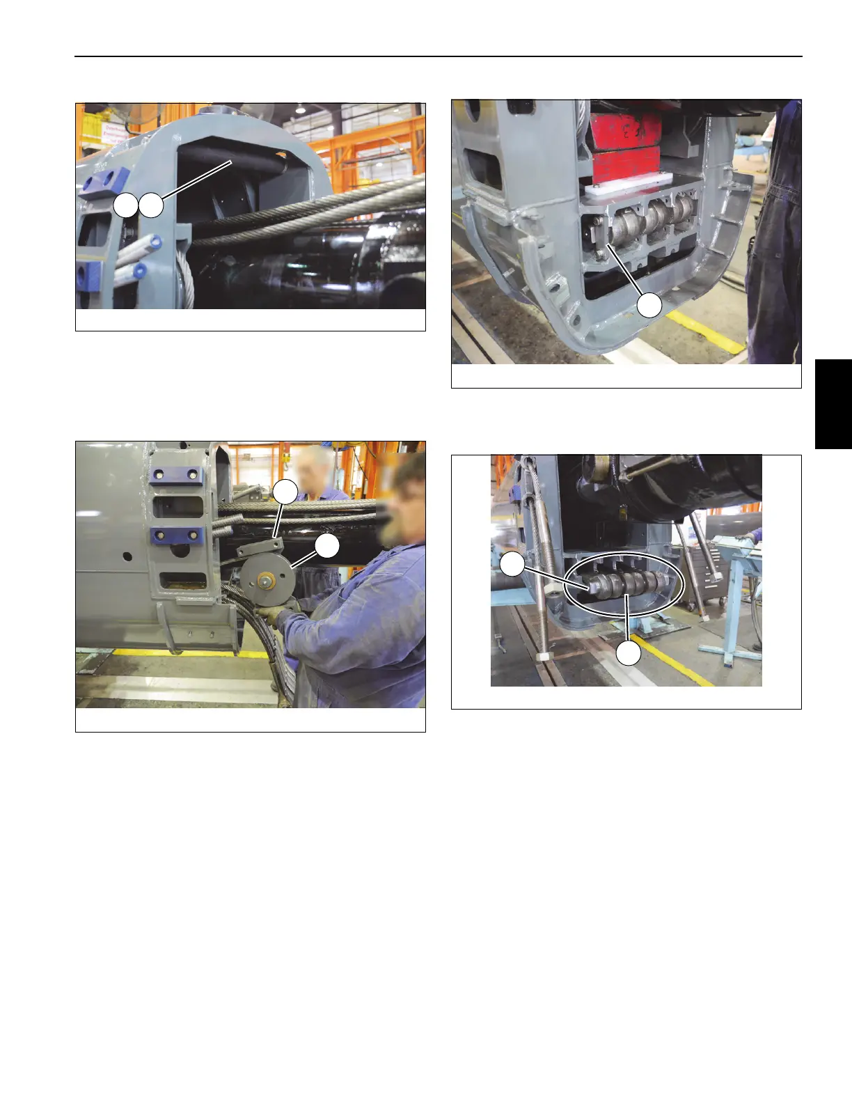
63. Remove grease fitting (109) from shaft of sheave mount
weldment (112) (left and right sides).
64. Remove four capscrews (113) and flat washers (16)
securing sheave assembly (81, 112) to rear of tele 3 (4)
(left and right sides) (see Figure 4-28).
65. Remove sheave assembly (81, 112) from rear of tele 3
(4). Remove thrust washers (83) and sheave weldment
(81) from shaft of sheave mount weldment (112).
Remove tele 3 retract cable (114) from around sheave
weldment (81) (left and right sides) (see Figure 4-28).
66. Remove two capscrews (123) securing wear pad (53) to
each sheave mount weldment (112).
67. Remove two capscrews (56), lockwashers (120), and
flat washers (119) securing keeper plate (118) to rear of
tele 3 (4) (left and right sides) (see Figure 4-29).
68. Remove shaft (117), which is holding the anchor ends of
the six tele 3 extend cables (139), from its keeper at rear
of tele 3 (4) (see Figure 4-30).
69. Slide shaft (117) out of anchor ends of the six tele 3
extend cables (139).
70. Push each cable anchor end back into tele 3 (4) and
pass it through the opening at top of tele 3 (4). Re-install
shaft (117) through all six anchor ends.
71. Secure ends of the six tele 3 extend cables (139) to the
top and bottom of telescope cylinder (6) using the
special tool (p/n MT102668) and a strap (see
Figure 4-31).

 Loading...


