BOOM GRT8100 SERVICE MANUAL
4-26
Published 3/26/2018, Control # 596-05
72. Begin to remove tele 4 (5) from tele 3 (4), ensuring
telescope cylinder (6) passes through rear of tele 3
without damaging tele 3 and telescope cylinder (6).
73. Extend tele 4 (5) out from tele 3 (4) approximately one-
quarter of its overall length.
74. Using an adequate lift and sling, slightly raise the front of
tele 4 (5).
75. Remove three capscrews (13) and flat washers (10)
securing keeper plate (20) to front of tele 3 (4) (left and
right sides) (see Figure 4-32).
76. Remove wear pad assembly (100) from front of tele 2 (3)
(left and right sides) (see Figure 4-32).
77. Slightly lower tele 4 (5).
78. Remove four bolts (13) and flat washers (10) securing
keeper plate (77) to front of tele 3 (4) (left, right, and
center) (see Figure 4-32).
79. Remove two bolts (18) securing stop block (14) and
shim (15) to front of tele 3 (4) (left and right sides) (see
Figure 4-32).
80. Remove wear pads (98, 2x-96, 2x-99) and shims (2x-97)
from front of tele 3 (4) (see Figure 4-32).
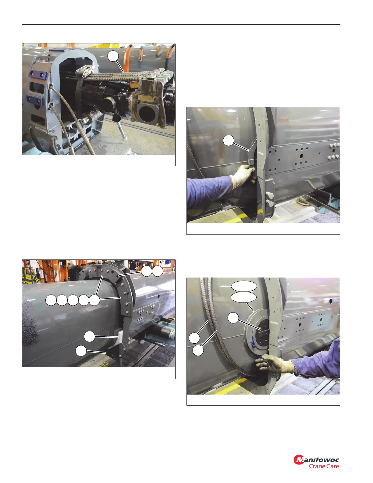
81. Remove capscrew (141) securing front guard weldment
(106) to tele 3 (4). Remove front guard (106) (left and
right sides) (see Figure 4-33).
82. Remove six bolts (108) securing front shaft (101) and
sheave assembly (102) to tele 3 (4). Pull tele 4 extend
cable (104) out the front of tele 3 (4), then remove shaft
(101) and sheave assembly (102) (left and right sides)
(see Figure 4-34).
83. Remove capscrew (141) securing rear guard weldment
(107) to tele 3 (4). Remove guard weldment (107) (left
and right sides).
FIGURE 4-32
8804-23
20
100
77
1514
99989697
FIGURE 4-34
8804-19
102
Front
103
Rear
105
104
101

 Loading...


