4-27
Published 3/26/2018, Control # 596-05
GRT8100 SERVICE MANUAL BOOM
84. Remove six bolts (108) securing rear shaft (101) and
sheave assembly (103) to tele 3 (4). Pull tele 4 extend
cable (105) out the front of tele 3 (4), then remove shaft
(101) and sheave assembly (103) (left and right sides)
(see Figure 4-34).
85. Remove tele 4 (5) from tele 3 (4). Set tele 4 (5) on
adequate supports.
86. Remove wear pad (132) and shim (130) from the rear of
the tele 4 (5) (left and right sides) (see Figure 4-35).
87. Detach grease hose assembly (66, 69, 171) from wear
pad (131) at rear of tele 4 (5) (left and right sides)
(Figure 4-35).
88. Remove two capscrews (129) securing wear pad (2x-
128) from rear of tele 4 (5) (see Figure 4-35).
89. Remove two capscrews (31) and wear pad (127) from
the rear of tele 4 (5) (see Figure 4-35).
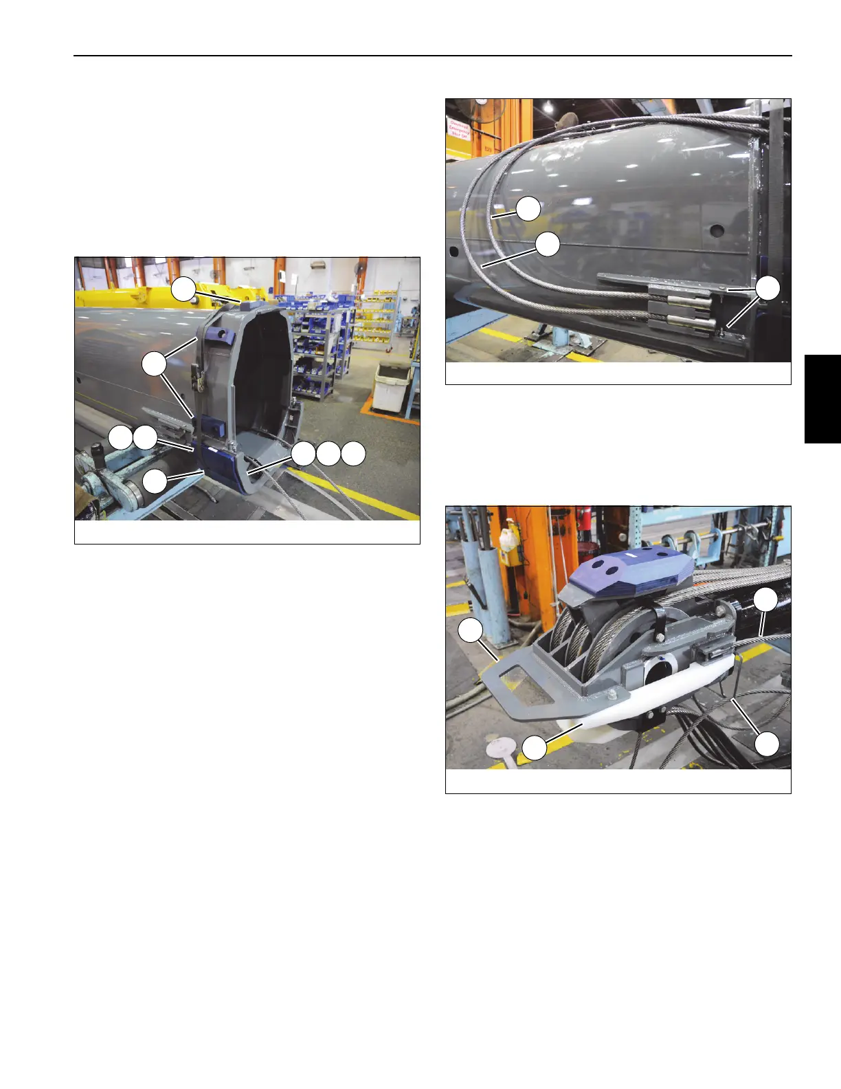
90. Remove four bolts (31) securing anchor ends of tele 4
extend cables (2x-104, 2x-105) to sides of tele 4 (5),
then Detach anchor ends of four tele 4 extend cables
(2x-104, 2x-105) from rear of tele 4 (5) (left and right
sides) (see Figure 4-36).
91. Remove telescope cylinder (6) from tele 4 (5). Set
telescope cylinder (6) on to adequate supports.
92. Remove two capscrews (146), four flat washers (10),
two lock washers (11), and two nuts (12) securing wear
pad (145) to side of telescope cylinder sheave mounting
weldment (133) (left and right sides) (see Figure 4-37).
93. Detach tele 4 retract cable (114) from side of telescope
cylinder sheave mounting weldment (133), then pull
cable back through cable keeper (A) on telescope
cylinder sheave mounting weldment (133) (left and right
sides) (see Figure 4-37).
94. Remove four nuts (49) and two washers (48) from ends
of two tele 4 retract cables (114) at front of tele 4 (5).
Remove two tele 4 retract cables (114) from inside of
tele 4 (5) (see Figure 4-38).
FIGURE 4-35
8804-14
130
69 171
132
66
131
127
128
FIGURE 4-36
8804-19
104
105
31
FIGURE 4-37
8008-6
A
114
145
133

 Loading...


