BOOM GRT8100 SERVICE MANUAL
4-44
Published 3/26/2018, Control # 596-05
114.Continue to insert tele 1 (2) into base section (1) until
wear pads and shims strapped to tele 1 (2) are near the
front of the base section (1). Lift and lower tele 1 (2) as
necessary until wear pads and shims slip into base
section (1), then remove strap. Continue to insert tele 1
(2) into base section (1) until wear pads and shims are
fully inserted.
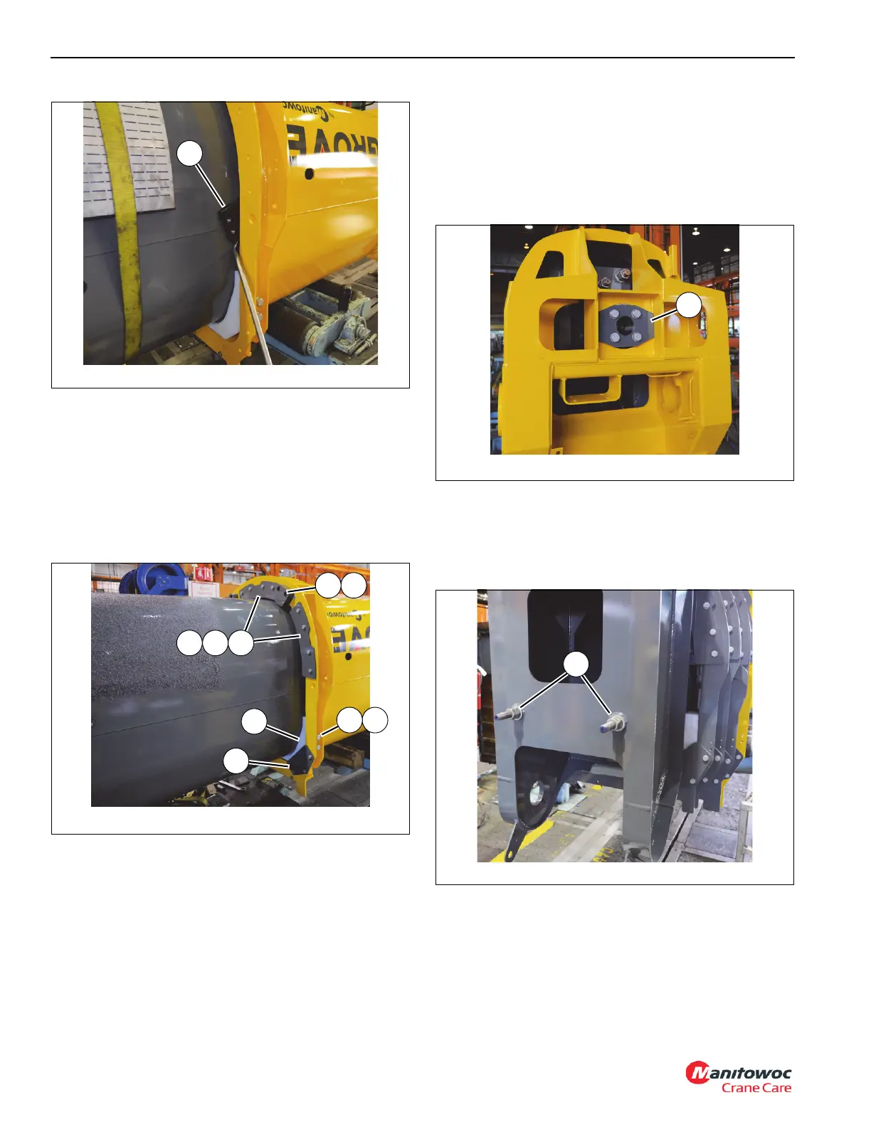
115.Install wear pad assembly (19) into the front of the base
section (1) (left and right sides) (see Figure 4-97).
116.Install eight wear pad adjusting capscrews (22) and nuts
(21) into front of base section (1). Run capscrews (22) in
until wear pad assemblies (19) touch tele 1 (2) (left and
right sides) (see Figure 4-97).
117.Install three keeper plates (77) to front of base section
(1) using twelve bolts (13) and flat washers (10) (left,
right, and center) (see Figure 4-97).
118.Install two stop blocks (14) and shims (15) to front of
base section (1) using four bolts (18) (see Figure 4-97).
119.Continue to insert tele 1 (2) into base section (1),
ensuring telescope cylinder (6) seats into the hole in the
rear of the base section. Remove special tool (part
number MT102678) from end of telescope cylinder.
120.Install plate (35) to rear of telescope cylinder (6) using
four bolts (22) and hardened flat washers (33) (see
Figure 4-98).
121.Remove the two wooden blocks from inside front of tele
4 (5) which are supporting telescope cylinder (6).
122.Adjust nuts (49) on front of tele 4 (5), which secure the
two tele 4 retract cables (114) in place, so that there are
82 mm. of exposed threads (see Figure 4-99).
123.Roll boom assembly to an upright position. As boom
assembly is being rolled upright, look inside front of tele
4 (5) and ensure the tele 4 retract cable (114) does not
catch on any part of tele 4 (5) section.
124.Mount tele stage selection manifold (39) to bottom rear
of base section (1) using four bolts (40).
FIGURE 4-97
8804-48
15
87
20
19
77
14
2221

 Loading...


