4-43
Published 3/26/2018, Control # 596-05
GRT8100 SERVICE MANUAL BOOM
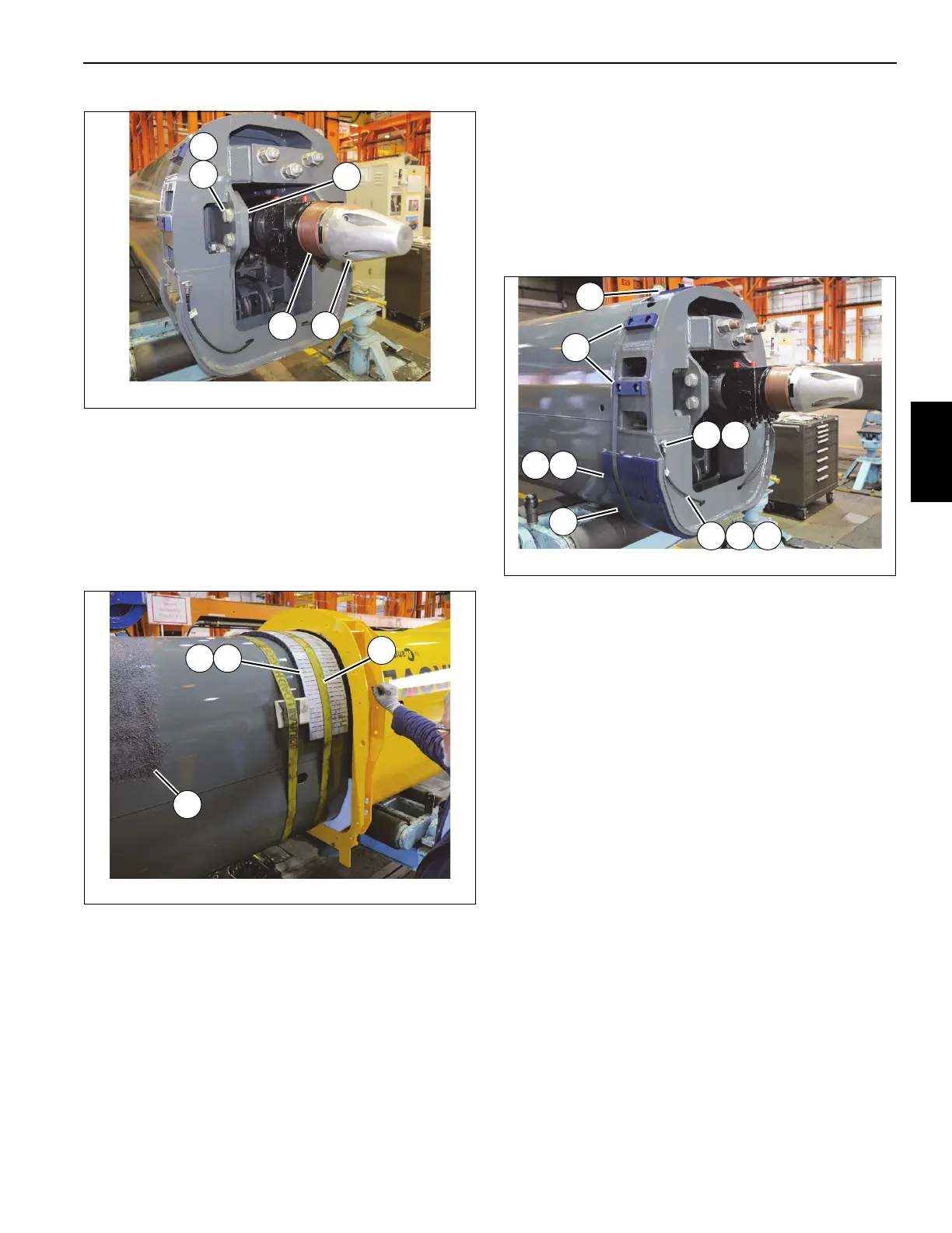
104.Apply anti-seize to machined surface (S) at rear of
telescope cylinder (6) (see Figure 4-93).
105.Attach special tool (p/n MT102678) (T) to end of
telescope cylinder (6) (see Figure 4-93).
106.Spray multipurpose grease (U) on outside of tele 1 (2).
Measuring approximately 1/4 of the distance of the
boom from the front tip, leave a 5 ft. wide strip of boom
free of grease to install wear pads (see Figure 4-94).
107.Place wear pad (7) and two shims (8) against tele 1 (2)
and secure them using a strap. Place two blocks of
wood or similar, with rubber pads on both sides, directly
in front of and against the wear pads and shims and
secure them with a strap (V) (see Figure 4-94).
108.Mount wear pad (2x - 53) and wear pad (4x - 54) to rear
of tele 1 (2) using capscrews (56) (see Figure 4-95).
NOTE: When installing tele 1 (2) into base section 1, add
equal number of shims (55) underneath wear pads
(53, 54) such that the wear pads are within 2 mm of
the bottom and sides of base section (1).
109.Install grease fitting assembly (67) to rear of tele 1 (2)
using nut (68). Orient grease fitting such that it is
perpendicular to tele 1 (2) (see Figure 4-95).
110.Attach grease hose (70) to grease fitting assembly (67)
at rear of tele 1 (2). Route hose through access hole in
tele 1. Attach grease hose (70) to wear pad (63) using
elbow (69) and adapter (66) (left and right sides)
(Figure 4-95).
111. Secure all wear pads (63, 64) and shims (65) to tele 1 (2)
using a strap. Place strap around edge of wear pads
farthest from rear end of tele 1 (2) (see Figure 4-95).
112.Position base section (1) up side down and in back of
tele 1 (2). Set base section (1) on adequate supports.
113.Insert tele 1 (2) in to base section (1) until wear pads
strapped to front of tele 1 are close to the front tip of the
base section. Install plate (167) between tele 1 and base
section and secure with four capscrews (168) and
hardened flat washers (16) (left and right sides) (see
Figure 4-96).
FIGURE 4-93
8804-46
S T
148
73
72
FIGURE 4-95
8804-53
65
69 70
64
63
66
54
53
6867

 Loading...


