BOOM GRT8100 SERVICE MANUAL
4-42
Published 3/26/2018, Control # 596-05
slip into tele 1 (2), then remove strap. Continue to insert
tele 2 (3) into tele 1 (2) until wear pads and shims are
fully inserted.
95. Install two wear pad assemblies (46) into the front of tele
1 (2). Ensure the two tele 3 retract cables (87) exit
between the two wear pad assemblies (46) (see
Figure 4-89).
96. Install eight wear pad adjusting capscrews (22) and nuts
(21) into front of tele 1 (2) (left and right sides). Run
capscrews (22) in until wear pad assemblies (46) touch
tele 2 (3) (see Figure 4-90).
97. Install three keeper plates (9) to front of tele 1 (2) using
twelve bolts (13) and flat washers (10) (left, right, and
center) (see Figure 4-90).
98. Install two stop blocks (14) and shims (15) to front of tele
1 (2) using four bolts (18) (left and right sides) (see
Figure 4-90) (see Figure 4-90).
99. Continue to insert tele 2 (3) into tele 1 (2) until anchor
weldment (47) with two tele 3 retract cables (87) secured
to it is near front of tele 1 (2).
100.Attach anchor weldment (47) to tele 1 (2) using four
capscrews (22) and flat washers (50) (see Figure 4-91).
101.Continue to insert tele 2 (3) into tele 1 (2), ensuring
telescope cylinder (6) passes through rear of tele 1
without damaging tele 1 and telescope cylinder (see
Figure 4-92).
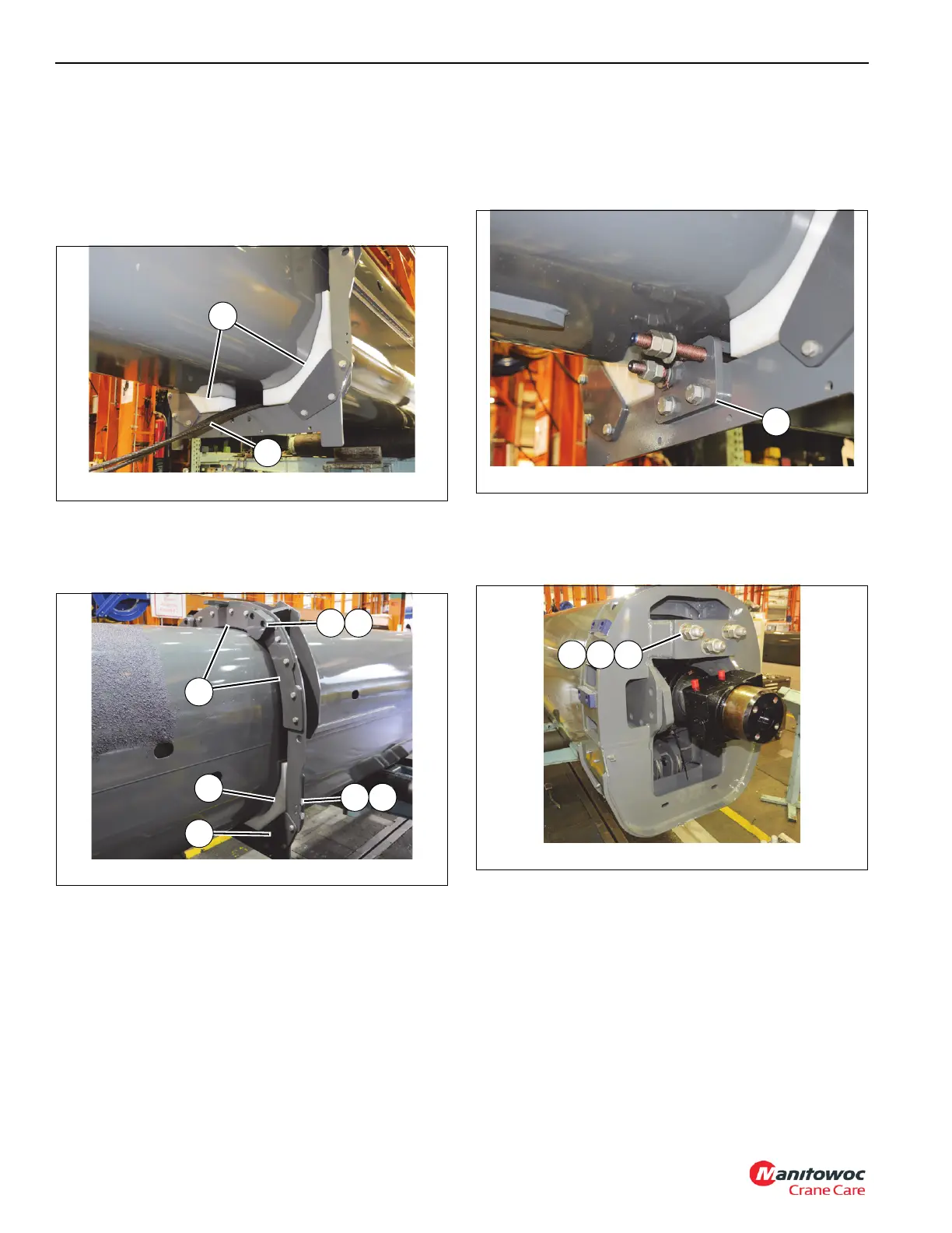
102.Install three large bolts (58) through holes in back of tele
1 (2). Install three hardened flat washers (59) and six
nuts (60) on to three bolts (58), leaving 55 mm of
exposed threads (see Figure 4-92).
103.Secure trunnion block (148) to tele 1 (2) using six bolts
(73) and hardened flat washers (72) (left and right sides)
(see Figure 4-93).
FIGURE 4-90
8804-54
15
28
46
9
14
2221
FIGURE 4-92
8804-47
60 59 58

 Loading...


