4-41
Published 3/26/2018, Control # 596-05
GRT8100 SERVICE MANUAL BOOM
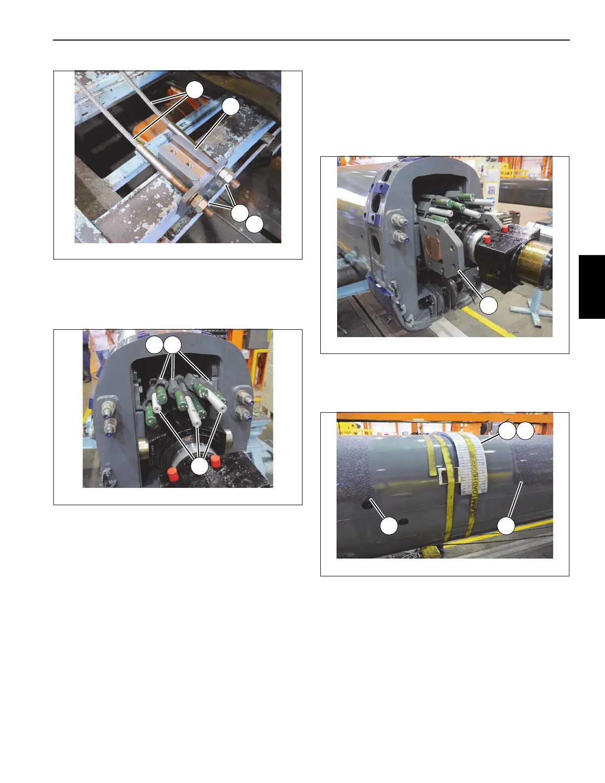
84. Install tele 3 extend cables (139) marked 1 and 2 into
anchor block (57), then install keeper plate (61) using
two capscrews (62). Repeat this procedure, grouping
tele 3 extend cables (139) marked 3 and 4 together and
the cables marked 5 and 6 together (see Figure 4-86).
85. Install three bolts (58) through anchor blocks (57) (see
Figure 4-86).
86. Mount six wear pads (54) to rear of tele 2 (3) using
twelve capscrews (56).
NOTE: When installing tele 2 (3) into tele 1 (2), add equal
number of shims (55) underneath wear pads (54)
such that the wear pads are within 2 mm of the
bottom and sides of tele 1 (2).
87. Install grease fitting assembly (67) to rear of tele 2 (3)
using nut (68). Orient the grease fitting such that it is
perpendicular to tele 2 (3) (left and right sides).
88. Attach grease hose (70) to grease fitting assembly (67)
at rear of tele 2 (3). Route hose through access hole in
tele 2. Attach grease hose (70) to wear pad (94) using
the elbow (69) and adapter (66) (left and right sides).
89. Secure all of loose wear pads (94, 95) and shims (93) to
tele 2 (3) using a strap. Place strap around edge of wear
pads farthest from rear end of tele 2 (3).
90. Apply anti-seize to rear trunnions at rear of telescope
cylinder (6). Install trunnion blocks (148). Zip-tie the two
trunnion blocks to the telescope cylinder (see
Figure 4-87).
91. Spray multipurpose grease (R) on outside of tele 2 (3).
Measuring approximately 1/4 of the distance of the
boom from the front tip, leave a 5 ft. wide strip of boom
free of grease to install wear pads (see Figure 4-88.
92. Place wear pad (76) and two shims (75) against tele 2
(3) and secure them using a strap. Place two blocks of
wood or similar, with rubber pads on both sides, directly
in front of and against the wear pads and shims and
secure them with a strap (see Figure 4-88).
93. Position tele 1 (2) up side down and in back of tele 2 (3).
Set tele 1 (2) on adequate supports.
94. Insert tele 2 (3) into tele 1 (2) until wear pads and shims
strapped to tele 2 (3) are near front of tele 1 (2). Lift and
lower tele 2 (3) as necessary until wear pads and shims
FIGURE 4-85
8804-42
47
48
49
87
FIGURE 4-86
8804-43
61 57
58
FIGURE 4-88
8804-58
R R
7675

 Loading...


