BOOM GRT8100 SERVICE MANUAL
4-40
Published 3/26/2018, Control # 596-05
78. Apply anti-seize to shaft (89), then install the roller (90)
and shaft (89) into rear of tele 2 (3). Index shaft (89) so
that it can be secured in place using two capscrews (85)
and flat washers (91) (see Figure 4-82).
79. Evenly lay out two tele 3 retract cables (87) beneath tele
2 (3), ensuring the anchor ends of the cables are
positioned to the rear of tele 2 (3).
80. Route anchor ends of the two tele 3 retract cables (87)
through holes at rear of tele 2 (3). Loop cable ends
around and secure to rear of tele 3 (4) using two plates
(166, 173), capscrews (121), and lock washers (11) (see
Figure 4-83).
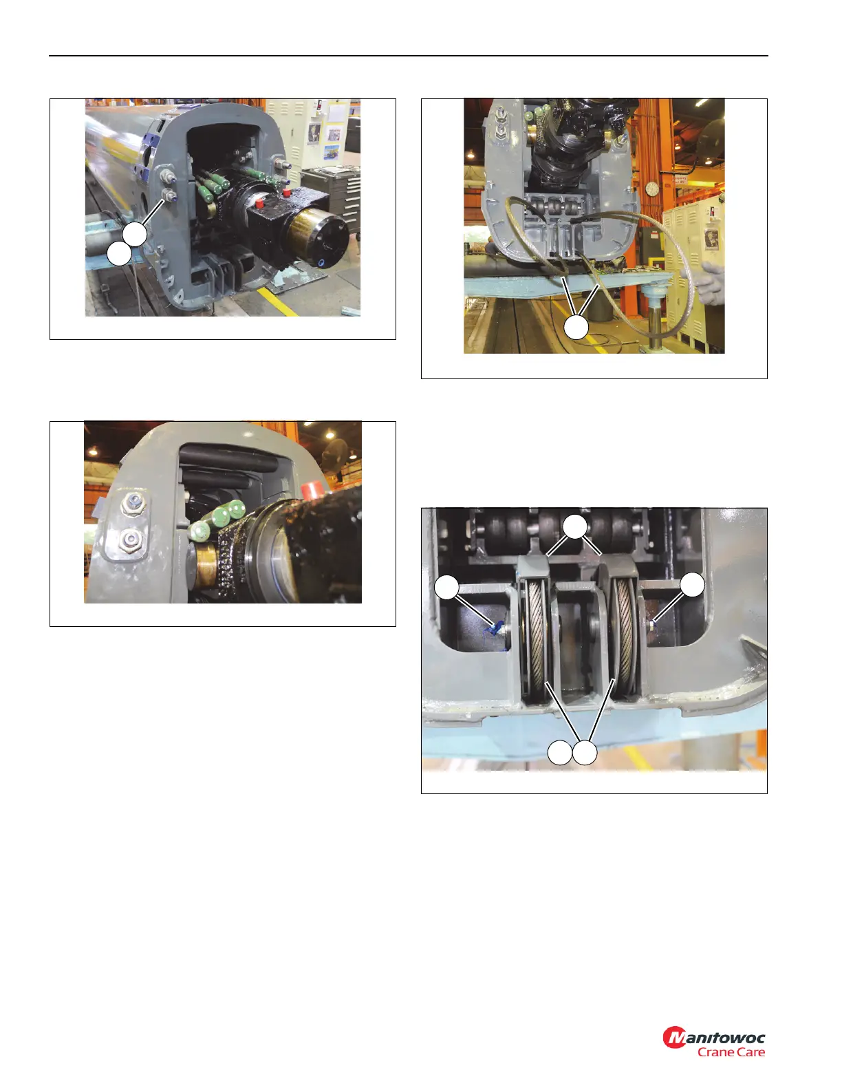
81. At rear of tele 2 (3), wrap two tele 3 retract cables (87)
around sheave assemblies (81), then install sheave
assemblies, guard weldments (84), and thrust washers
(83) in to rear of tele 2 and secure in place with shaft
weldments (82). Secure two shaft weldments (82) in
place using two capscrews (85) and lock washers (28).
(see Figure 4-84).
82. Install grease fitting (86) on to shaft assembly (82) (left
and right sides). Add grease until grease extrudes
through the sheaves.
83. At front of tele 2 (3), insert the threaded ends of the two
tele 3 retract cables (87) through holes in anchor
weldment (47). Apply anti-seize to threads of both
cables, then install four nuts (49) and two washers (48),
leaving 42 mm. of thread exposed on each cable end
(see Figure 4-85).
FIGURE 4-84
8804-41
84
83 81
82
82

 Loading...


