4-39
Published 3/26/2018, Control # 596-05
GRT8100 SERVICE MANUAL BOOM
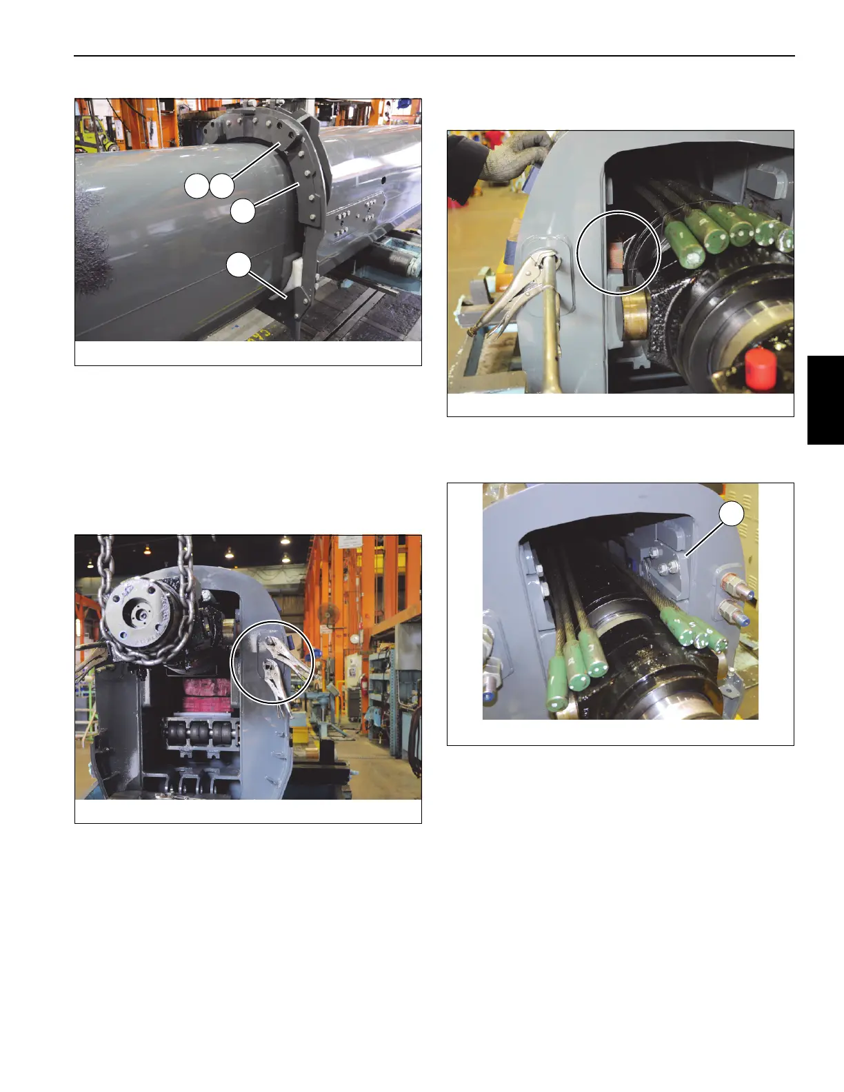
73. Install two stop blocks (14) and shims (15) to front of tele
2 (3) using four bolts (18) (left and right sides) (see
Figure 4-77).
74. Continue to insert tele 3 (4) into tele 2 (3), ensuring
telescope cylinder (6) passes through the rear of tele 2
without damaging tele 2 and the telescope cylinder, and
that the threaded rods on ends of the four tele 4 extend
cables (104, 105) pass through the four holes in rear of
tele 2 (3) (see Figure 4-78).
75. Lift rear of telescope cylinder (6) and remove blocks of
wood. Lower cylinder so that its front trunnion blocks
(148) drop into the pockets at inside rear of tele 2 (3)
(see Figure 4-79).
76. Install trunnion plate (92) using the three capscrews (22)
and flat washers (33) (left and right sides) (see
Figure 4-80).
77. Apply anti-seize to threaded ends of the four tele 4
extend cables (2x - 104, 2x - 105). Install eight nuts (88)
and four washers (72) on to the ends of the cables.
Adjust nuts such that there are 62 mm. of exposed
threads on all four cable ends. (see Figure 4-81).
FIGURE 4-77
8804-19
15
77
14
20

 Loading...


