6-11
Published 3/26/2018, Control # 596-05
GRT8100 SERVICE MANUAL SWING SYSTEM
3. Multiplier bar handles must be propped or supported
within the outer 1/4 of the handle length, or serious
under or over tightening will occur.
4. The inner race of the bearing is secured to the turntable
by a quantity of 71, 24 mm x 160 mm, 10.9 grade bolts.
The outer race of the bearing is secured to the carrier
frame by a quantity of 72, 24 mm x 160 mm, 10.9 grade
bolts.
Tools Required
The figure Figure 6-3 illustrates and lists the complete set of
special tools required to torque the turntable bolts.
Inner Race Torquing
1. Extend and set the outriggers. Fully elevate the boom.
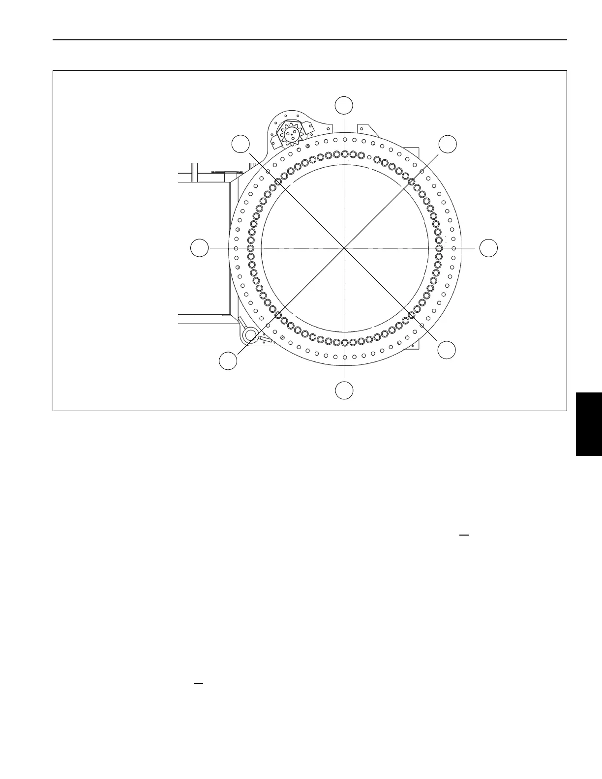
2. Torque eight bolts to 80% of their specified torque value
using the sequence pattern shown in Figure 6-2; refer to
Fasteners and Torque Values, page 1-15 for proper
torque value. Tools used are the socket, multiplier,
backlash adapter, necessary extensions, and torque
wrench.
3. Return to bolt 1 and torque all
bolts sequentially in a
clockwise direction to their final torque value specified.
The same tools are used as in step 2.
Outer Race Torquing
1. Extend and set the outriggers. Fully elevate the boom.
2. Torque eight bolts to 80% of their specified torque value
using the sequence pattern shown in Figure 6-2; refer to
Fasteners and Torque Values, page 1-15 for proper
torque value. Tools used are the socket, multiplier,
backlash adapter, necessary extensions, and torque
wrench.
3. Return to bolt 1 and torque all
bolts sequentially in a
clockwise direction to their final torque value specified.
The same tools are used as in step 2.
Removal
1. Fully extend and set the outriggers enough to take up
the slack in the pads.
NOTE: Do not raise the machine on the outriggers.
2. Ensure the boom is in the travel position and the
turntable lock pin is engaged.
3. Elevate the boom slightly and shut down the engine.
4. Tag and disconnect the battery cables from the
batteries.
FIGURE 6-2
8804-136
3
1
4
2
7
6
8
5
Front of Crane
 Loading...


