9-21
GRT8100 SERVICE MANUAL LUBRICATION
Published 3/26/2018, Control # 596-05
Boom (Continued)
NOTE: Crane Setup: Machine shall be set up on firm level surface with fully extended outriggers and minimum 9979 kg
(22,000 lb) counterweight installed. Ensure crane is level.
• Boom must be directly over the front with house lock engaged.
• Set boom angle at zero degrees (0°).
• Do not exceed 35 m (115 ft) boom length in Auto Mode A.
• Do not exceed 27.4 m (90 ft) boom length in Auto Mode B.
• All lubrication points can be accessed by operating crane in the 0001 RCL mode using A or B boom configurations.
CAUTION: Do not operate crane in RCL bypass to lubricate the boom.
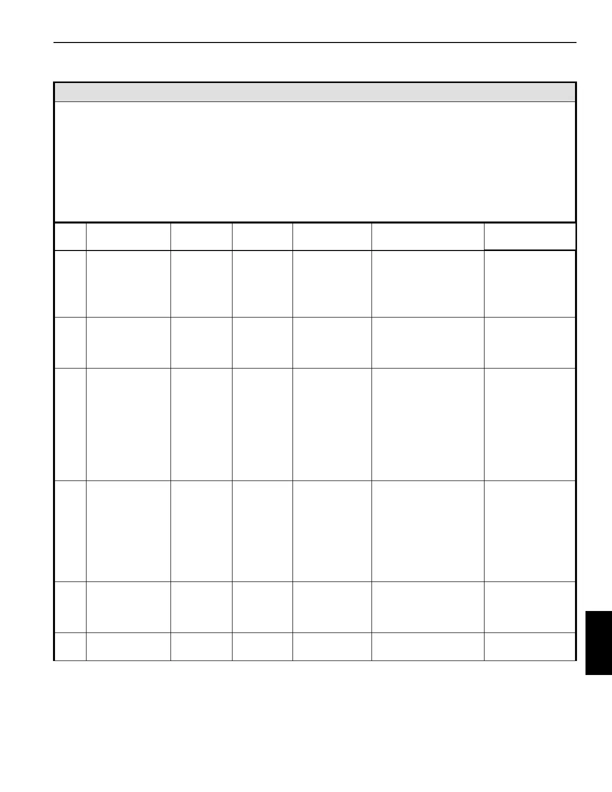
Item
Lube Point
Description
Figure No.
Approved
Lubricant
Lube Capacity Lube Interval Application
83
Telescope
Cylinder Wear
Pads
Figure 9-12 L Coat thoroughly
Apply grease at
assembly or tear-down.
• 12 places
• Extend boom for
access through
holes in side of
sections 3 & 4
84
Internal Side and
Bottom Wear
Pads - Inner
Sections
Figure 9-12
&
Figure 9-13
L
Thoroughly
coat all areas
wear pad
moves on
250 hours/3 months 23 locations
85A
Boom Section
Rear Upper
Wear Pads - Tele
1
Figure 9-12 L
Thoroughly
coat all areas
the wear pad
moves on
50 hours/1 week
• 2 locations
• Extend Tele 1 to
17.6 meters
(57.8 FT) and
20.7 Meters
(67.8 FT) so
access holes
align with the
grease fittings.
85B
Boom Section
Rear Upper
Wear Pads - Tele
2 - 4
Figure 9-12
&
Figure 9-13
L
Thoroughly
coat all areas
wear pad
moves on
50 hours/1 week
• 6 locations
• Extend Tele 2 to
38.1 Meters
(124.9 FT) so
the access
holes align with
the grease
fittings.
86
Boom Section
Lower & Upper
Wear Pads
Figure 9-12
&
Figure 9-13
L
Thoroughly
coat all areas
wear pad
moves on
50 hours/1 week 12 locations
87
Extend Cable
Sheave
Figure 9-12 A
Until grease
extrudes
250 hours or 3 months 6 locations
 Loading...


