HYDRAULIC SYSTEM GRT9165 SERVICE MANUAL
2-60
Published 10-01-2020 Control # 699-00
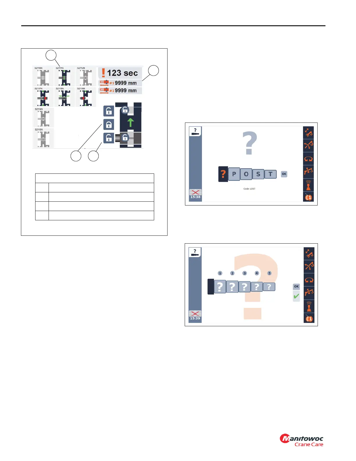
The Boom Recovery screen appears.
5. Make sure cylinder 1 (1, Figure 2-29) is at 0 mm (2).
a. If cylinder 1 is not at 0 mm, unlock the cylinder using
the cylinder unlock button (3) and the jog dial
selector.
b. Use the joystick and retract cylinder 1 (1) until the
length reads 0 mm (2).
c. Make sure that cylinder 1 (S2111N) (1) is green.
d. If it is not green, use the lock button (4) and the jog
dial to lock the boom and verify that cylinder 1
(S2111N) (1) is green.
Tele Extend
1. Gradually extend the cylinder until the cylinder is fully
extended and hold.
2. Slowly accelerate the engine to full RPM. The reading at
Port 4 should be 2900 ±100 PSI (200 ±7 bar). If it is not,
adjust the Tele extend relief (2, Figure 2-26) “in” to
increase or “out” to decrease until the reading is
achieved.
Tele Retract
1. Gradually extend the cylinder until the cylinder is fully
extended and hold. Slowly accelerate the engine to full
RPM. The reading at port 4 should be the value cited in
Table 2-3. If it is not, adjust the Tele retract relief (2,
Figure 2-26) “in” to increase or “out” to decrease until the
reading is achieved
2. Make sure that the cylinder is fully retracted, length
reads 0 mm.
3. Return the boom pinning to its normal state.
4. Navigate to the Lower display menu screen and select
the Boom lost icon. (2, Figure 2-28).
The Boom Lost setup screen appears.
5. Use the jog dial or keypad to navigate to and change the
word “POST” to “LOST”, then select the “OK” box and
press down on the jog dial or OK button on the keypad.
The Boom Lost screen appears.
6. Navigate to each boom section and enter 0 for the
pinning position.
NOTE: Note: If the boom is not fully retracted enter to
appropriate pinning position for each section.
7. Select the “OK” button.
8. Stop engine. Remove diagnostic couplers.
Checking / Setting the Swing Brake Release
Pressure
1. With the engine off, install a pressure check diagnostic
quick disconnect (such as Parker PD240) with gauge
1
3
2
Boom Recovery Screen
1 Cylinder 1 (S2111N)
2 Cylinder 1 Length Indicator
3 Cylinder Unlock Button
4 Lock Button
FIGURE 2-29
4

 Loading...


