HYDRAULIC SYSTEM GRT9165 SERVICE MANUAL
2-54
Published 10-01-2020 Control # 699-00
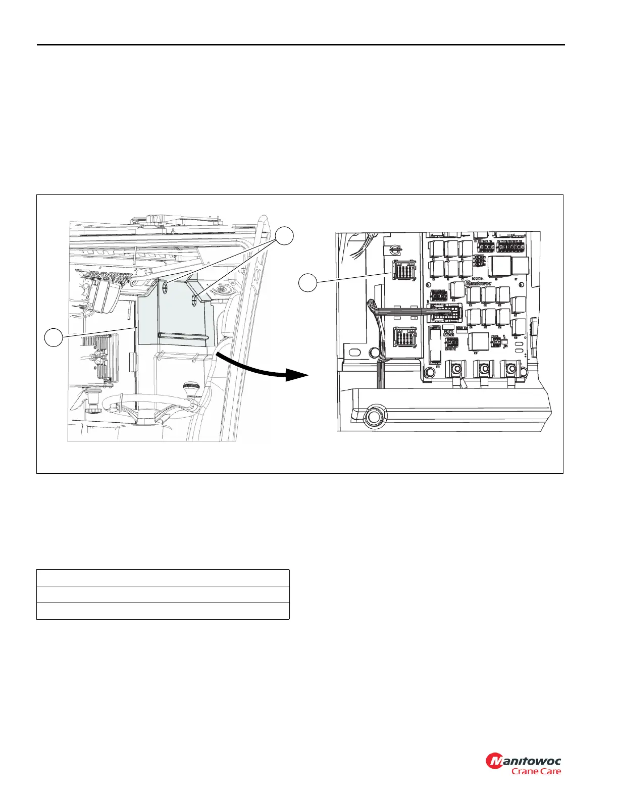
Accessing the Diagnostic Connector
The diagnostic connector (1, Figure 2-23) is located behind
the operator seat. The rear electrical upper cover (2) must be
removed to access the diagnostic connector.
Removing the Upper Electrical Cover
1. Move the operator seat as necessary to access the
upper cover (2, Figure 2-23).
2. Turn the thumb screws (3).
3. Remove the upper electrical cover (2).
Installing the Upper Electrical Cover
1. Move the operator seat as necessary to access the
upper cover (2, Figure 2-23).
2. Install the cover (2) over thumbscrews (3). Make sure
the edges of the cover fits securely.
3. Turn the thumbscrews (3) to secure the cover (2).
Connecting the Manitowoc Crane Service
Tool
Use the following procedure to connect the diagnostic cable
and Manitowoc Crane Service Tool to the crane diagnostic
port.
1. Remove the upper electrical cover. For more
information, see Removing the Upper Electrical Cover,
page 2-54.
2. Connect the USB end of the diagnostic cable to the PC.
3. Connect cOSI connector to the diagnostic port (1,
Figure 2-23).
4. Launch the Manitowoc Crane Service Tool.
Checking/Setting the Piston Pumps Cut-off
and Differential Pressures
Use the following procedure to check and set the cut-off and
differential pressures for both piston pumps (1 and 2,
Figure 2-25).
NOTE: Make sure the outrigger box pressure bleed off
valve is shut before checking the cut-off and
differential settings. For more information, see the
Operator Manual.
1. Install a pressure check diagnostic quick disconnect
(Parker PD240 or equivalent) with gauge onto test
nipple in the GP port of the main directional control valve
(1, Figure 2-26).
2. Adjust the piston pump cutoff maximum on both piston
pumps (1 and 2, Figure 2-25) as follows:
a. Make sure the piston pump cut-off maximum (3,
Figure 2-25) factory setting is correct. Loosen the
jam nut on the cut-off maximum adjusting screw.
Required Equipment
PC with Manitowoc Crane Service tool installed.
Diagnostic Cable.

 Loading...


