8-7
GRT9165 SERVICE MANUAL UNDERCARRIAGE
Published 10-01-2020 Control # 699-00
Rear Steer Sensor Adjustment Procedure
Use the following procedure the adjust the rear steer sensor.
A proximity switch on the rear axle senses the position of the
rear wheels. If the wheels are not centered, a signal is sent to
the ODM, which displays the Rear Wheels Not Centered
Indicator in the Alerts area of the ODM. For more information
about steering configurations and the ODM, see the
Operator Manual.
1. Ensure the wheels are straight ahead.
NOTE: When performing rear steer indicator adjustment
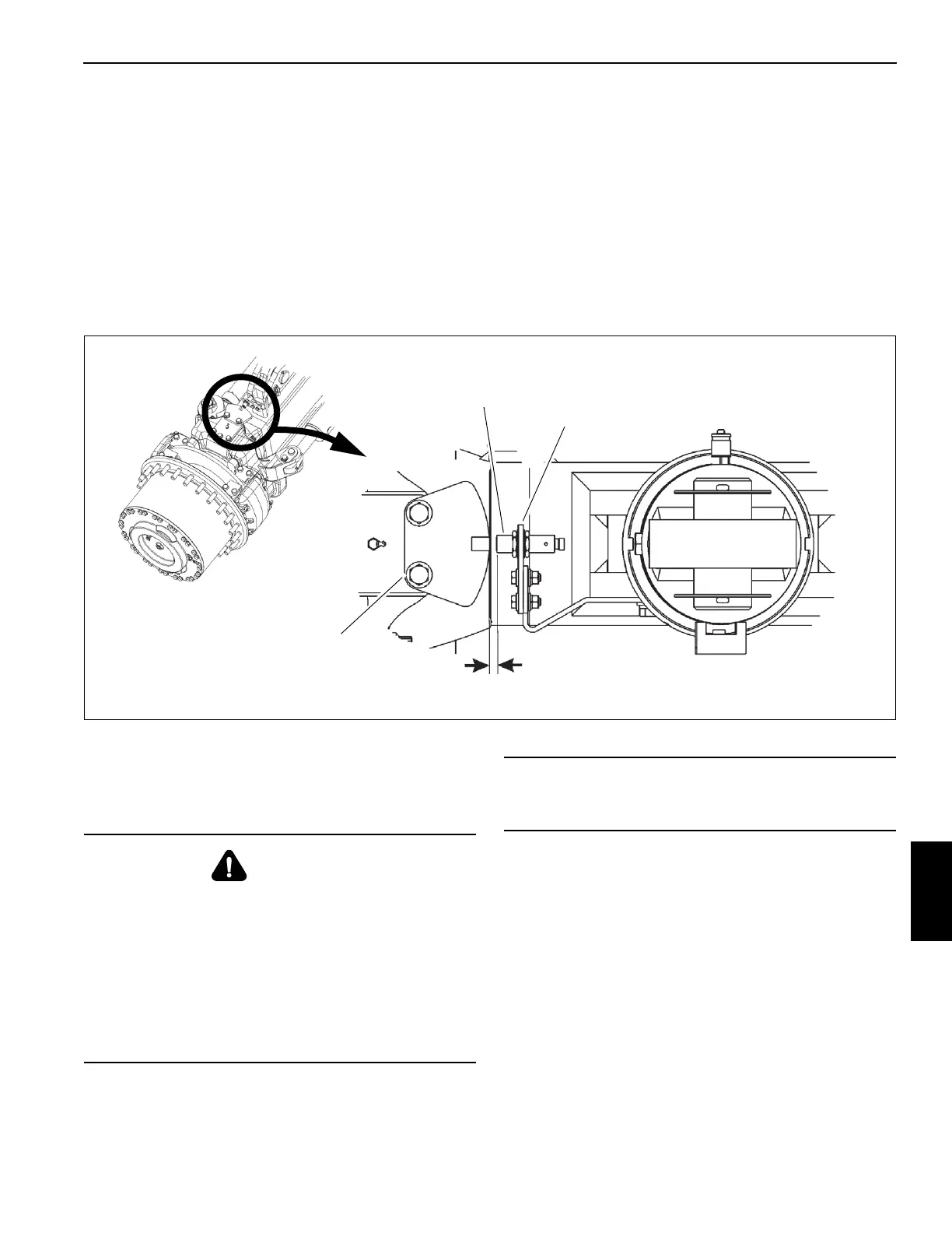
using the following steps, refer to Figure 8-6.
2. Slide the proximity switch through hole in the mounting
bracket and secure with nuts and washers.
3. Set face of proximity switch from 4 mm (0.16 in) to 6 mm
(0.24 in) from opening in rear steer sensor plate. Tighten
the fasteners.
4. Turn the rear wheels to verify proper operation. Rear
Wheels Not Centered Light in cab should be out when
rear wheels are centered and the sensor switch is
centered in the slot of the sensor plate. Adjust proximity
switch in or out as needed.
Wheels And Tires
Description
The standard tire size for this unit is 26.5x25-44 ply.
Each wheel assembly (tire and rim) is mounted on the
planetary hub with 24 3/4-16UNF lug nuts.
NOTE: The tire diameters, widths, and weights may vary
slightly depending on the tire manufacturer.
Off-highway tires are designed to operate with a certain
sidewall deflection or bulge. Correct air pressure ensures
prior deflection which, in turn, ensures proper traction,
flotation, support of load, and prevents excessive flexing of
the tire. Over inflation increases rim stresses, which results
in lowered rim life.
Refer to and adhere to the inflation pressures in the Load
Chart Book in the crane cab.
4 mm to 6 mm
Sensor Plate
Mounting Bracket
Proximity Switch
FIGURE 8-6
(0.16 in to 0.24 in)
10225
10226
WARNING
Possible equipment damage and/or
personal injury!
Driving the crane with a tire under inflated at 80% or less
of its recommended pressure can cause the wheel and/or
tire to fail. Per OSHA Standard 1910.177(f)(2)(i), when a
tire has been driven under inflated at 80% or less of its
recommended pressure, it must first be completely
deflated, removed from the axle, disassembled, and
inspected before re-inflation.
CAUTION
Do not mix tires or rims from different manufacturers.
Vehicle stability can be affected.

 Loading...


