8-13
GRT9165 SERVICE MANUAL UNDERCARRIAGE
Published 10-01-2020 Control # 699-00
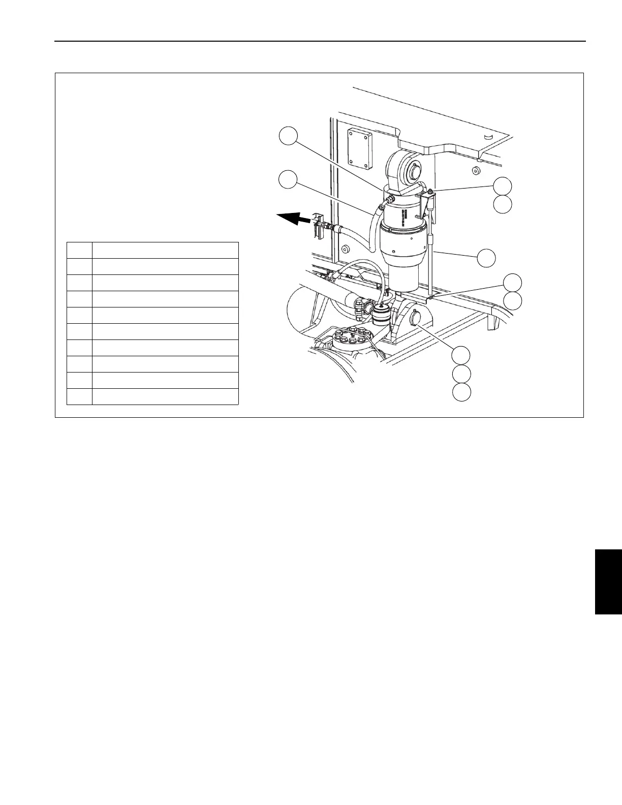
Removing the Hydraulic Strut
1. Remove the wheels. For more information, see Wheels
And Tires, page 8-7.
2. Add a block or rigging under the axle to support the
axle’s weight.
3. Remove the hydraulic hose (10, Figure 8-10). Cap the
hydraulic hose (10).
4. Remove nut (3) and washer (4) from the top length
sensor bracket.
5. Remove nut (5), washer (6), and length sensor (2) from
bottom length sensor bracket.
NOTE: The hydraulic strut weighs approximately 72.6 kg
(160 lb).
6. Remove cotter pins (7), spacers (8), suspension pin (9),
and strut (1) from the axle.
Installing the Hydraulic Strut
NOTE: The hydraulic strut weighs approximately 72.6 kg
(160 lb).
1. Install the bottom of the strut (1) on the axle with spacers
(8), suspension pin (9), and cotter pins (7).
2. Install the length sensor (2) on to the bottom of the strut
(1) bracket with washer (6) and nut (5).
3. Install the length sensor (2) on to the top strut (1) bracket
with washer (4) and nut (3).
4. Uncap and install hydraulic hose (10).
5. Remove blocks or rigging from under the axle.
6. Install wheels. For more information, see Wheels And
Tires, page 8-7.
BRAKE SYSTEM
Description
The brake system includes all the components necessary for
the application of the service brakes and the parking brake.
Service Brakes
The service brakes are full power hydraulic brakes which are
hydraulically controlled and are used to apply the brake
assemblies on all six wheels. The system consists of the
tandem brake valve with treadle pedal, the dual accumulator
FIGURE 8-10
2
1
To Suspension
Manifold Valve
3
4
5
6
7
1 Hydraulic Strut
2 Length Sensor
3Nut
4 Washer
5Nut
6 Washer
7 Cotter Pin
8 Spacer
9 Suspension Pin
10 Hydraulic Hose
8
9
10
10230

 Loading...


