2-51
GRT9165 SERVICE MANUAL HYDRAULIC SYSTEM
Published 10-01-2020 Control # 699-00
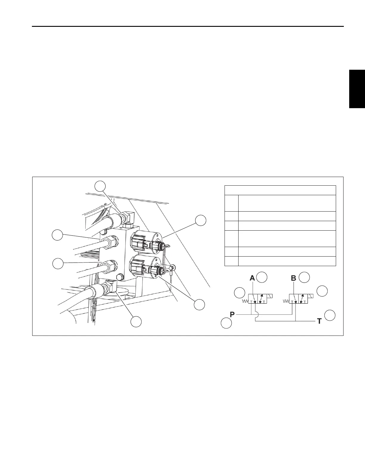
HYDRAULIC BOOM EXTENSION VALVE
(OPTIONAL)
When installed, the hydraulic boom extension valve
(Figure 2-22) is located on the upper right side of the
superstructure. This valve controls the flow of hydraulic fluid
to the hydraulic boom extension, if installed.
Removal
1. Start the engine and fully retract the telescope the lift
cylinders using the joysticks. Use the RCL override
function to fully retract the lift cylinder.
2. Raise the hydraulic boom extension to 0° offset.
3. Shut off engine.
4. Tag and remove hydraulic hoses from the hydraulic
boom extension manifold valve.
5. Tag and disconnect electrical connects.
6. Remove capscrews, lockwashers, washers, and
hydraulic boom extension manifold from bracket.
Installation
1. Install hydraulic boom extension manifold valve on
bracket with capscrews, washers, lockwashers, and
nuts.
2. Connect hydraulic hoses as tagged.
3. Connect electrical connectors as tagged.
Functional Test
1. Start the engine and run it at normal speed.
2. Raise and lower the boom extension. Check for smooth
operation of cylinders and motors.
3. Check the valve bank(s) and lines for leakage. Make
repairs as needed.
FIGURE 2-22
4
1
2
3
5
6
Hydraulic Boom Extension Valve
1
Pressure Port — P (from P2 Port on
Compact Manifold Valve)
2 Solenoid Valve — Move Raise
3 Solenoid Valve — Move Lower
4
Tank Port — T (fromT2 Port on
Compact Manifold Valve)
5 Work Port — B — Lower
6 Work Port — A — Raise
1
2
3
4
5
6
10132 10133

 Loading...


