8-15
GRT9165 SERVICE MANUAL UNDERCARRIAGE
Published 10-01-2020 Control # 699-00
General
A schedule for the periodic adjustment, cleaning, inspection,
and lubrication of brake equipment should be established by
the operator on the basis of past experience and severity of
operation.
The disc brakes are not adjustable. Brakes should be
cleaned, inspected, and linkage lubricated periodically to
assure maximum performance.
Bleeding the Brake System
The brake system should be bled whenever air becomes
entrapped within the brake system (usually characterized by
a spongy feeling during brake pedal application), whenever
any brake system line has been opened, or whenever any
brake component has been replaced.
Always start at the point in the system that is furthest from
the tandem brake valve and work back toward the tandem
brake valve. Bleed every bleeder screw on every caliper/
actuator on every wheel. When you complete a bleeder
screw, go to the next closest bleeder screw on the same
caliper/actuator. When you complete a wheel, go to the
furthest bleeder screw on the next closest wheel.
Manually Bleeding the Brake System
NOTE: Before bleeding the brake system, ensure the
hydraulic accumulators are fully charged.
1. Connect the end of the bleeder hose to the bleed screw
on the caliper. Submerge the other end in a jar partially
filled with clean hydraulic oil.
2. Open the bleed screw on the caliper/actuator and allow
fluid to flow into the jar, while depressing the brake
pedal. Depress the brake pedal and close the bleeder
screw, then release the brake pedal. Torque the bleeder
screw 11.3 N-m to 13.6 N-m (100 lb-in to 120 lb-in).
3. Repeat step 2 until a solid stream free of air bubbles is
obtained.
4. Repeat steps 1 thru 3 for the remaining wheel calipers/
actuators.
SERVICE BRAKES
Description
The brakes utilized on the axles are hydraulic disc-type
brakes. Two brake assemblies are used at the end of each
axle. The action of the brake pads pressing against the brake
discs acts to slow the rotation of the wheels.
Maintenance
NOTE: To perform maintenance on the brake caliper,
remove the tire and wheel assembly. Refer to
Axles, page 8-1 in this section.
Removal
Linings
1. Block the wheels.
2. Remove the bolts securing the end plates to one side of
the caliper housing. Remove the end plates.
3. Loosen the bleeder screws to release hydraulic
pressure in the caliper.
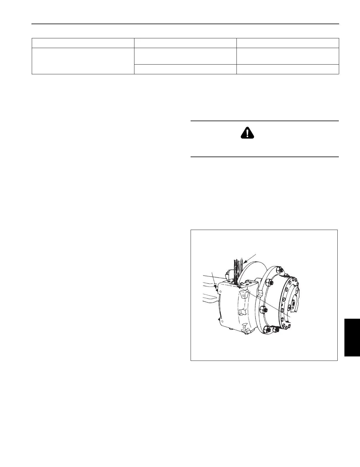
4. Use a piece of wood against the linings as a pry bar to
push the pistons completely into the housing. Tighten
the bleeder screws Figure 8-11. Torque the bleeder
screw 11.3 N-m to 13.6 N-m (100 lb-in to 120 lb-in).
5. Remove the linings from the caliper housing. If
necessary, discard the linings.
4. Uneven braking or pad wear. a. Lining thickness less than
0.125 in (3 mm).
a. Replace the lining.
b. Grease on the pads/linings. b. Replace the pads/linings.
Symptom Probable Cause Solution
CAUTION
To prevent serious eye injury, always wear eye protection
when doing maintenance or service.
FIGURE 8-11
Wood Block
Loosen
Bleeder
Screws
Push wood
block against
linings to push
pistons into
bores

 Loading...


