HYDRAULIC SYSTEM GRT9165 SERVICE MANUAL
2-28
Published 10-01-2020 Control # 699-00
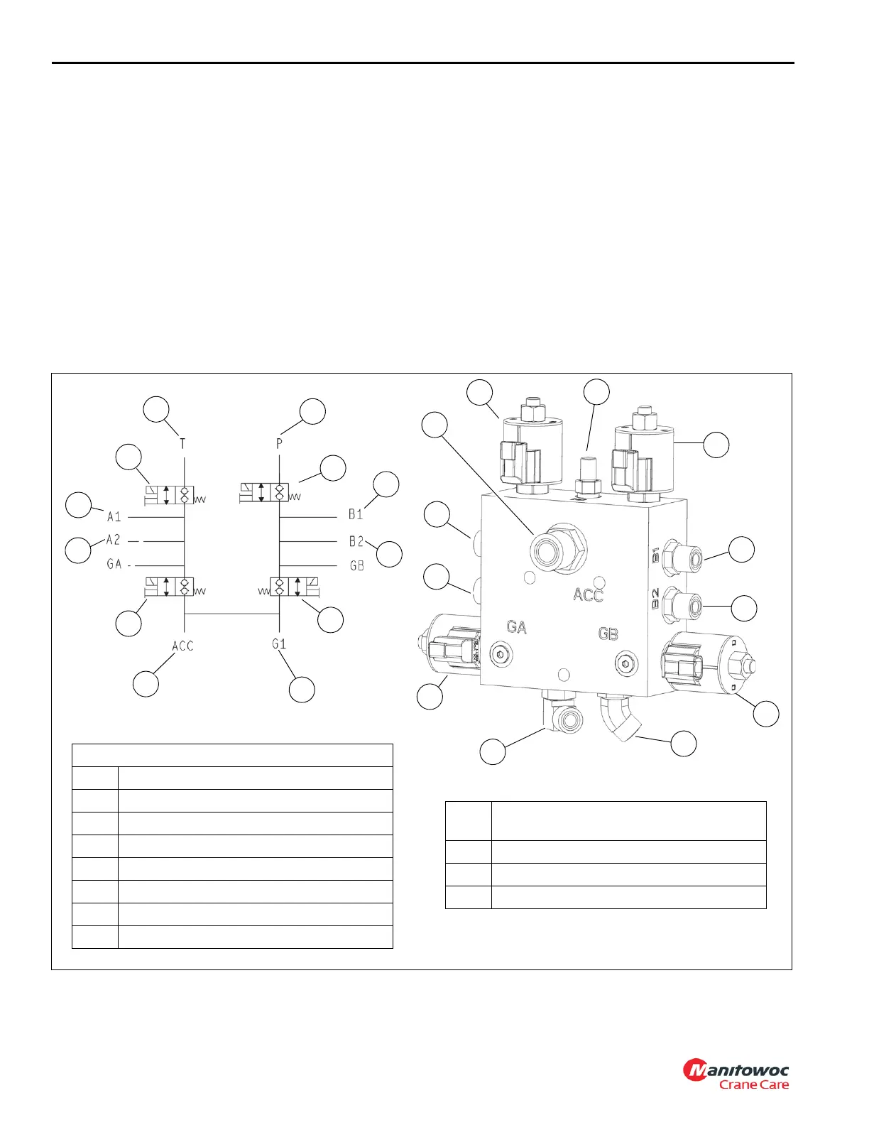
Suspension Manifold Valve
The suspension manifold valve controls the flow of oil to the
suspension system, locks out the suspension, and connects/
disconnects the suspension to a damping/oscillation
accumulator (Figure 2-9). The valve is located on the center
of the carrier frame near the turntable bearing (Figure 2-6).
Pressure is supplied to the valve from the carrier manifold
valve.
Removal
1. Tag and disconnect electrical connectors to the valve.
2. Tag and disconnect hydraulic hoses from the valve. Cap
or plug lines and ports.
3. Remove capscrews, lockwashers, flatwashers, and nuts
securing valve to the frame. Remove valve.
Installation
1. Secure valve to frame with nuts, flatwashers,
lockwashers, and capscrews. Torque capscrews - refer
to Fasteners and Torque Values, page 1-16 for proper
torque value.
2. Connect hydraulic hoses to ports on valve as tagged
during removal.
3. Connect electrical connectors to valve as tagged during
removal.
Functional Tests
1. Start and idle engine.
2. With unit on outriggers, check for proper two/four wheel
operation.
10102
FIGURE 2-9
1
2
3
4
5
6
7
8
1
2
3
4
5
6
7
10103
8
9
10
11
12
9
10
11
12
Suspension Manifold Valve
1 Inlet Port — P
2 Tank Port — T
3 B2 Port — Right Center Cylinder
4 B1 Port — Right Rear Cylinder
5 Gauge Port — G1
6A1 Port
7A2 Port
8 Accumulator Port
9
Solenoid Valve — Suspension Fill from
SUS port on Carrier Manifold valve.
10 Solenoid Valve — Return
11 Solenoid Valve — Solenoid
12 Solenoid Valve — Lower

 Loading...


