2-47
GRT9165 SERVICE MANUAL HYDRAULIC SYSTEM
Published 10-01-2020 Control # 699-00
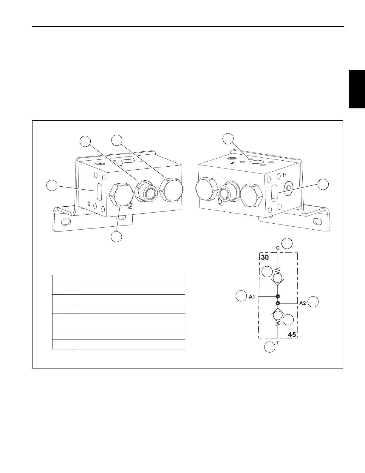
Check Valve Assembly
The check valve assembly (Figure 2-19) is located on the
right side of the superstructure (Figure 2-13).
Removal
1. Tag and disconnect the hydraulic lines from the valves.
Cap or plug the lines and ports.
2. Remove the capscrews, flatwashers, and lockwashers
securing the valve. Remove the valve.
Installation
1. Install the valve on the turntable upright and secure with
the capscrews, flatwashers, and lockwashers. Torque
capscrews. Refer to Fasteners and Torque Values, page
1-16 for proper torque value.
2. Connect the hydraulic lines to the valves as tagged
during removal.
3. Secure the valve using capscrews and nuts.
Check Valve Assembly
1 Check Valve - 30 PSI
2 Work Port - A2 to Compact Valve T1
3 Check Valve - 45 PSI
4
Work Port - A1 from Main Directional
Control Valve
5 Tank Port - Tank/return leg to swivel
6 Work Port - Tank/return leg to cooler
2
3
1
4
5
6
FIGURE 2-19
1
3
4
2
6
5
10125
10124
10126

 Loading...


