2-29
GRT9165 SERVICE MANUAL HYDRAULIC SYSTEM
Published 10-01-2020 Control # 699-00
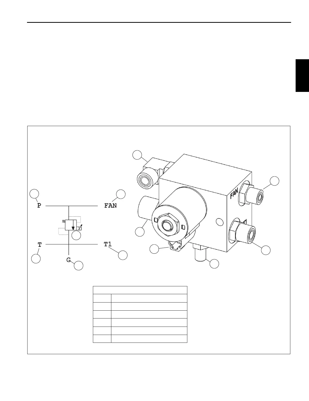
Fan Control Manifold Valve
The fan control manifold valve (Figure 2-10) controls the flow
of oil to the radiator fan motors. The fan control manifold
receives hydraulic oil from hydraulic pump #4.
Removal
1. Tag and disconnect electrical connectors to the valve.
2. Tag and disconnect hydraulic hoses from the valve. Cap
or plug lines and ports.
3. Remove capscrews, lockwashers, flatwashers, and nuts
securing valve to the frame. Remove valve.
Installation
1. Secure valve to frame with nuts, flatwashers,
lockwashers, and capscrews. Torque capscrews - refer
to Fasteners and Torque Values, page 1-16 for proper
torque value.
2. Connect hydraulic hoses to ports on valve as tagged
during removal.
3. Connect electrical connectors to valve as tagged during
removal.
Functional Tests
1. Start and idle engine.
2. With unit on outriggers, check for proper operation.
FIGURE 2-10
1
2
4
5
3
6
1
2
3
4
6
5
Fan Control Manifold
1 FAN Port — Output to Fans
2 T1 Port — Return from Fans
3 Gauge Port — G
4 Solenoid Valve — Fan
5 Tank Port — T
6 Inlet Port — P
10104
10105

 Loading...


