2-67
GRT9165 SERVICE MANUAL HYDRAULIC SYSTEM
Published 10-01-2020 Control # 699-00
more than 100 mA there may other issues in the
circuit.
b. Once the pressure is achieved make sure to “Save
active to customer” and “Save active to factory.”
Stop the engine.
Suspension Raise Pressure
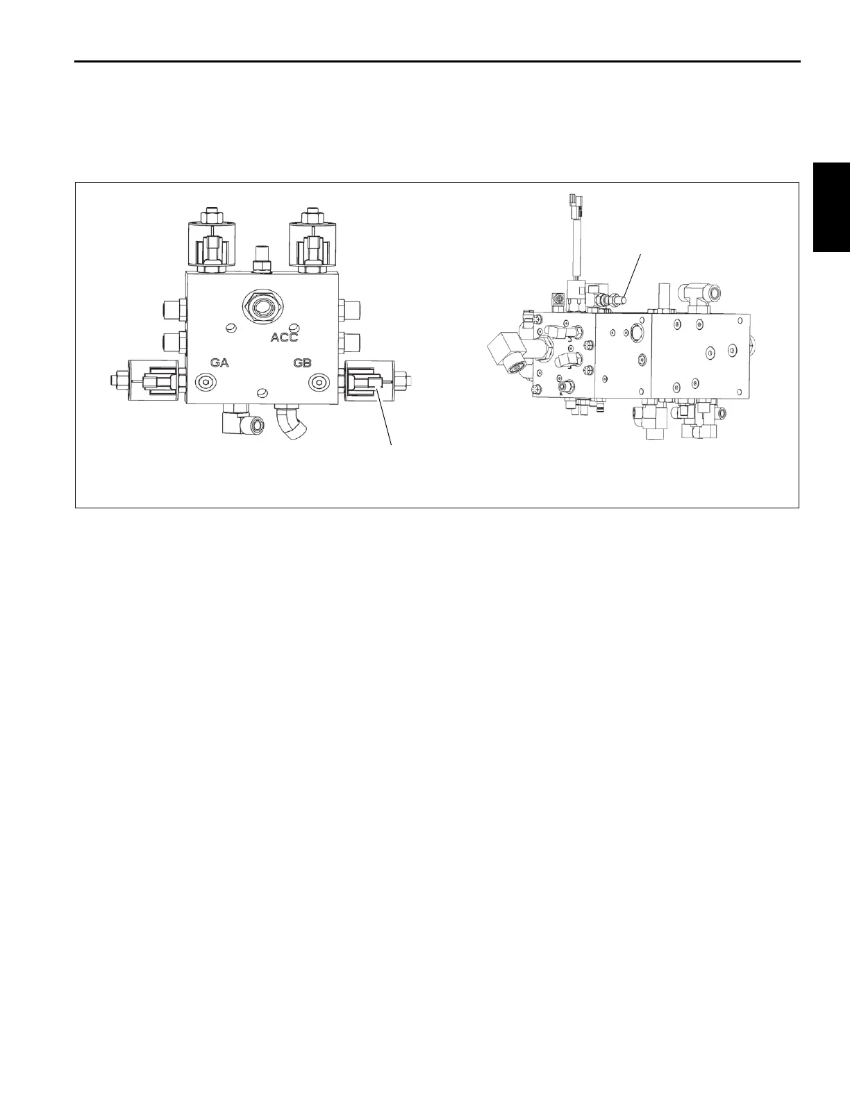
1. On suspension valve manifold (Figure 2-34), unplug the
coil on valve inlet port P. Start the engine and idle.
Operate the suspension fill function and hold. The
reading at LS port (1, Figure 2-33) should read the value
cited in Table 2-3. If it is not, use the service tool as
follows to adjust:
a. In the Manitowoc Crane Tool, open Tools > EEprom
> View Parameters > Cabin > Solenoid PWM
Control (carrier) > Pressure Sol – Suspension Raise
Target. In the params row, increase the valve to
increase the pressure or decrease the valve to
decrease the pressure (adjustment by 10 mA
increments is suggested). Make sure to write
column to “active settings”. Repeat this step until the
pressure is achieved. If the value needs adjusted by
more than 100 mA, there may other issues in the
circuit.
b. After the pressure is achieved make sure to “Save
active to customer” and “Save active to factory.”
2. Stop the engine. Plug the inlet coil in on the suspension
valve manifold.
Checking/Setting Park Brake Pressure and
Transmission Fan Max Pressure
1. With the engine off, install a pressure check diagnostic
coupler (such as a Parker PD240) with gauge onto the
diagnostic nipple at the PS port of the main carrier valve
(Figure 2-34).
2. Unplug transmission fan coil from harness (Figure 2-34).
3. Start engine and idle. Release (pressurize) the parking
brake. Read gauge and adjust the pressure reducing
valve (Figure 2-34) “in” to increase or “out” to decrease
to the value cited in Table 2-3.
4. With coil unplugged, and parking brake released, check
fan speed with photo tachometer. Fan speed should the
value cited in Table 2-3. Be sure to have the oil
temperature between 49 to 60°C (120 to 140°F) when
reading and adjusting.
5. Stop the engine. Remove the diagnostic couplers. Plug
fan coil back in to harness.
Adjusting Controller Functions
All controller defaults are set at the factory. If there is an
issue with the crane controller functions, try the following:
• Set all function pressure correctly per the above
procedures
• Adjust the function speed through the CCS control
screens
• Adjust the function control through the CCS control
screen selectable curves
Suspension Valve Manifold
Main Carrier Valve Manifold (Rear)
Unplug this coil to
set suspension
raise pressure
Park Brake/
Reducing Valve
Gauge Port
FIGURE 2-34
10143
10144

 Loading...


