POWER TRAIN GRT9165 SERVICE MANUAL
7-28
Published 10-01-2020 Control # 699-00
Drive Shafts
Removal
1. Support the drive shaft being removed so it does not fall
when disconnected. If removing the coupling shaft or the
forward slip shaft, support the other shaft also.
2. Remove capscrews (5, Figure 7-20), lockwashers (6),
nuts (7), and driveshaft (1) from the front axle.
3. Remove capscrews (8) and slip driveshaft (2) from
bearings assembly.
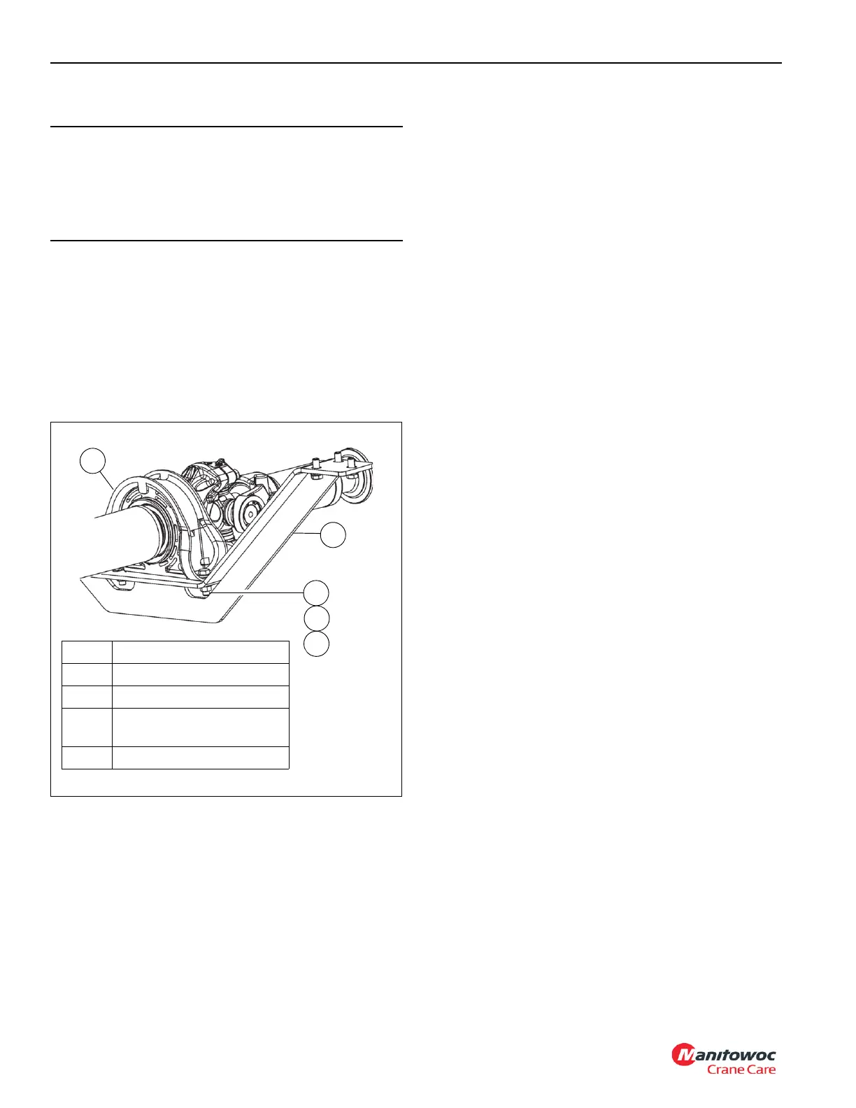
4. Remove capscrews (1, Figure 7-21), washers (2), nuts
(3), and driveshaft and bearing assembly (4) from the
carrier bearing weldment.
5. Remove capscrews (9, Figure 7-20), lockwashers (10),
nuts (11), and slip driveshaft (2) from the transmission.
6. Remove capscrews (9), lockwashers (10), nuts (11), and
driveshaft (3) from the transmission.
7. Remove capscrews (8) and slip driveshaft (4) from
driveshaft and bearing assembly.
8. Remove capscrews (1, Figure 7-21), washers (2), nuts
(3), and driveshaft and bearing assembly (4) from the
carrier bearing weldment.
9. Remove capscrews (8, Figure 7-20) and slip driveshaft
(4) from rear axle.
Installation
1. Install slip driveshaft (4, Figure 7-20) on rear axle with
capscrews (8). Torque capscrews (8) to 155.9 Nm
to183.0 Nm (115 ft-lb to 135 ft-lb).
2. Install driveshaft (3) on transmission with lockwashers
(10), capscrews (9), and nuts (11). Torque nuts (11) to
101.7 Nm to 128.8 Nm (75 to 95 ft-lb).
3. Install driveshaft (3) and bearing assembly (4,
Figure 7-21) on rear carrier bearing weldment (5) with
washers (2), capscrews (1), and nuts (3). Torque nuts to
66.2 Nm to 69.7 Nm (48.8 ft-lbs to 51.4 ft-lbs).
4. Install slip driveshaft (4, Figure 7-20) on the rear
driveshaft and bearing assembly with capscrews (8).
Torque capscrews (8) to 155.9 Nm to 183.0 Nm (115 ft-
lb to 135 ft-lb).
5. Install slip driveshaft (2) to transmission with capscrews
(9). washers (10), and nuts (11). Torque nuts to
101.7 Nm to 128.8 Nm (75 to 95 ft-lb).
6. Install driveshaft (1) on front axle with lockwashers (6),
capscrews (5), and nuts (7). Torque nuts (7) to 180.3 Nm
to 219.6 Nm (133 to 162 ft-lbs).
7. Install driveshaft (1) and bearing assembly (4,
Figure 7-21) on carrier bearing weldment (5) with
washers (2), capscrews (1), and nuts (3). Torque nuts to
66.2 Nm to 69.7 Nm (48.8 ft-lbs to 51.4 ft-lbs).
8. Install slip driveshaft (2, Figure 7-20) on the front
driveshaft and bearing assembly with capscrews (8).
Torque capscrews (8) to 155.9 Nm to 183.0 Nm (115 ft-
lb to 135 ft-lb).
Lubrication
The drive line slip joints require lubrication. Refer to
Maintenance and Lubrication, page 9-1.
TRANSMISSION
Description
The transmission assembly (1, Figure 7-23) is connected to
the engine torque converter with a driveshaft. The
transmission is connected to the front and rear axles by four
drive shafts.
CAUTION
Do not disassemble drive lines when removing them from
the crane. Dirt can enter the spline and cannot be purged.
In addition, the drive lines are assembled in a specific
orientation when manufactured and can easily be
incorrectly reassembled.
1
2
3
5
FIGURE 7-21
1 Capscrew M12x40 8.8
2 Washer
3Nut
4
Driveshaft and Bearing
Assembly
5 Carrier Bearing Weldment
4
10210

 Loading...


