POWER TRAIN GRT9165 SERVICE MANUAL
7-2
Published 10-01-2020 Control # 699-00
The air intake filter is mounted on the right rear fender. The
muffler is mounted on the left side of the carrier between the
rear axles.
The engine is equipped with electric air heating elements
located in the engine intake air stream to aid in cold starting
and reduce white smoke at start-up. In preheat mode, the
engine should not be cranked until Wait-to-Start Lamp turns
off. The Wait-to-Start Lamp is illuminated during the preheat
time that takes place when the ignition switch is in the ON
position during cold weather starting. The ECM checks
information it receives from various sensors on the engine to
determine how long to energize the air heater before
extinguishing the Wait-to-Start Lamp. Once the engine is
started, the electric air heating element will be energized
again for a time period determined by intake air temperature.
Maintenance
Engine Removal
1. Set outriggers and position boom over the side.
2. Rotate the superstructure so it is over the side of the
crane.
3. Open and remove hood top door assembly.
4. Disconnect air filter tubing at engine and air cleaner.
Remove and lay aside.
5. On Non-certified engines, disconnect exhaust tubing at
engine and muffler.
6. On Stage V/Tier 4 Final engines, disconnect the muffler
exhaust tubing at the engine and aftertreatment
assembly (muffler) remove the tubing from the engine.
Lay to the side.
7. Tag and disconnect engine electrical harness connector
from carrier harness connector and battery cables.
8. Unbolt fuel filter and engine lubrication filter from frame
and lay on the engine.
9. Drain engine coolant system.
10. Drain engine lubrication system.
11. Remove engine hood assembly and pump cover from
machine.
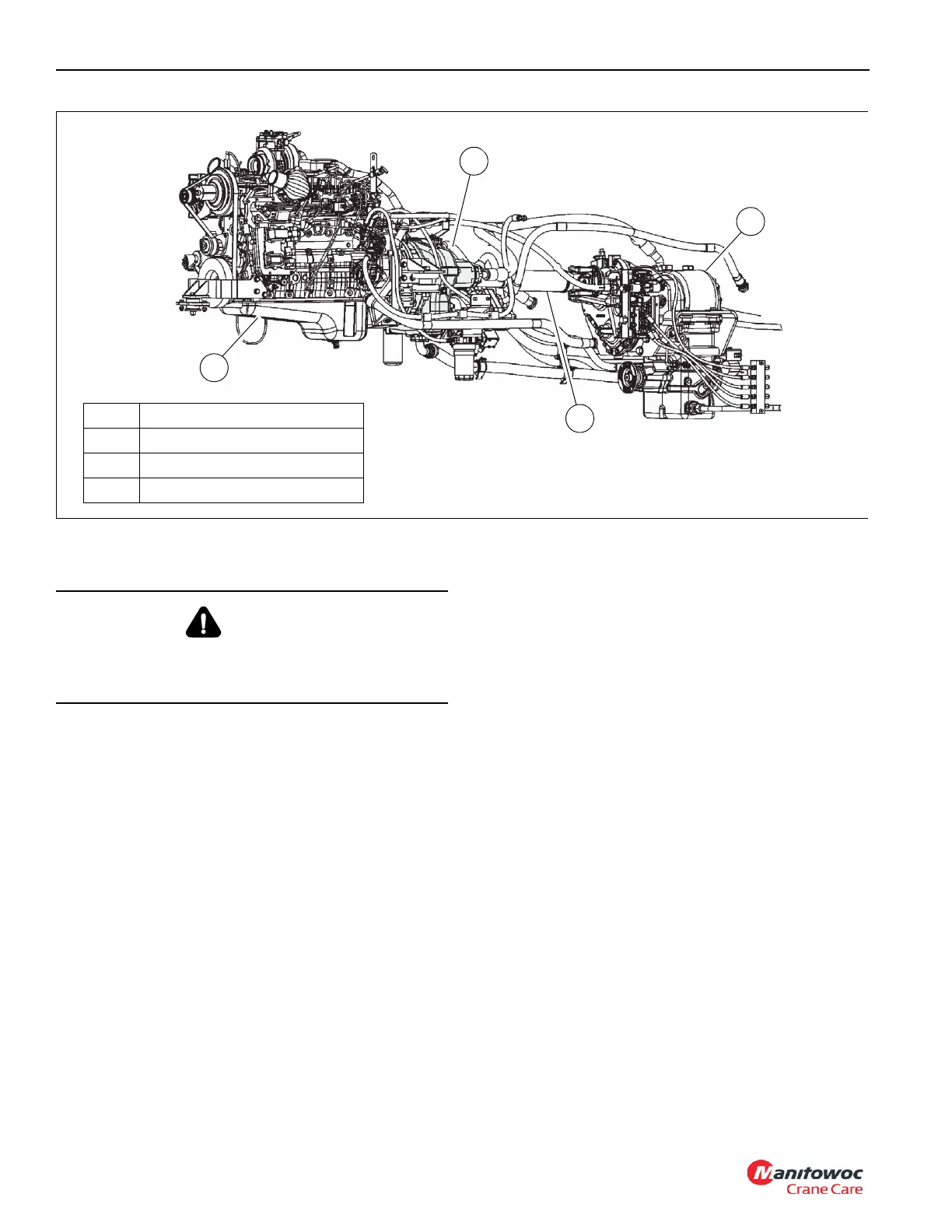
12. Remove capscrews, locknuts, and disconnect driveshaft
(4, Figure 7-1) from the transmission (3) flywheel.
13. Tag and disconnect all lines from the radiator. Discon-
nect coolant level sensor harness from engine harness.
Tie up excess harness so it is out of the way. Remove
radiator. Refer to Radiator Removal and Installation,
page 7-23 in this Section.
14. Tag and disconnect all lines and tubing from engine/
torque converter, and all other components. On Tier 4
Final / Stage V engines, tag and disconnect the DEF
coolant hoses.
1
2
3
FIGURE 7-1
4
1 Engine
2 Torque Converter
3 Transmission
4 Driveshaft
10176
WARNING
Do not spray starting fluid into the air inlet. The spray will
contact the heater elements and could explode causing
personal injury.

 Loading...


