2-55
GRT9165 SERVICE MANUAL HYDRAULIC SYSTEM
Published 10-01-2020 Control # 699-00
b. Back the adjusting screw out until there is 8.0 ±
0.5 mm (0.32 in ±0.02 in) from the end of the
adjusting screw to the top of the jam nut seated
against the valve body (see Cut-Off Screw
Adjustments in Figure 2-25). This adjustment
makes sure the full system pressure cited in
Table 2-3 can be obtained but limit the maximum
cutoff pressure of the pumps.
3. Do the following to make sure the piston pump
differential pressure (stand-by) is correct:
a. With diagnostic quick disconnect (Parker PD240 or
equivalent) still installed in the GP port of the main
directional control valve (1, Figure 2-26), start the
engine.
b. At idle RPM, adjust the piston pump 2 (4,
Figure 2-26) differential setting screw in to increase
or out to decrease so that a gauge reading cited in
Table 2-3 is achieved. It may be necessary to back
out the stand-by adjustment screw for pump 1 if the
pressure cannot be achieved.
c. With the engine still at idle RPM adjust the piston
pump 1 differential setting screw “in” to increase or
“out” to decrease so that a gauge reading cited in is
achieved.
4. Stop the engine. Remove the diagnostic coupler.
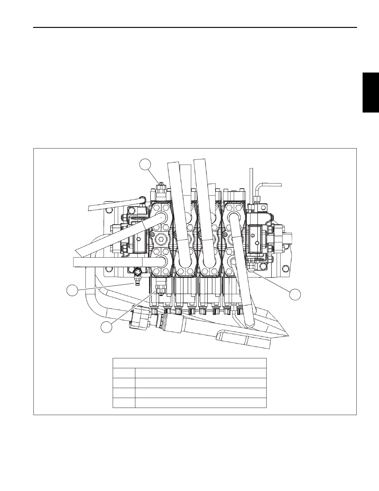
FIGURE 2-24
10136
Main Directional Valve
1 Main Directional Valve GP Diagnostic Port
2 Telescope Extend Relief
3 Telescope Retract Relief
4 LS Relief
2
1
3
4

 Loading...


