• DOK-DIAX02-DDS02.1*ANA-ANW1-EN-E1,44 • 12.96
24
2. The digital intelligent AC servo drive with ANALOG interface
Command communication
module with position
actual-value output
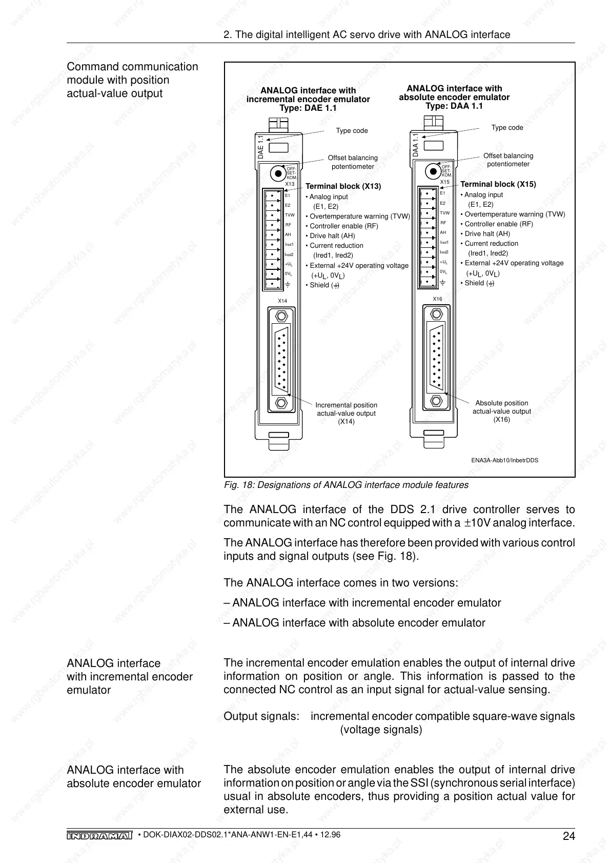
Fig. 18: Designations of ANALOG interface module features
The ANALOG interface of the DDS 2.1 drive controller serves to
communicate with an NC control equipped with a ±10V analog interface.
The ANALOG interface has therefore been provided with various control
inputs and signal outputs (see Fig. 18).
The ANALOG interface comes in two versions:
– ANALOG interface with incremental encoder emulator
– ANALOG interface with absolute encoder emulator
The incremental encoder emulation enables the output of internal drive
information on position or angle. This information is passed to the
connected NC control as an input signal for actual-value sensing.
Output signals: incremental encoder compatible square-wave signals
(voltage signals)
The absolute encoder emulation enables the output of internal drive
information on position or angle via the SSI (synchronous serial interface)
usual in absolute encoders, thus providing a position actual value for
external use.
ANALOG interface
with incremental encoder
emulator
ANALOG interface with
absolute encoder emulator
ENA3A-Abb10/InbetrDDS
Absolute position
actual-value output
(X16)
ANALOG interface with
absolute encoder emulator
Type: DAA 1.1
OFF-
SET-
KOM.
Ired2
+U
L
0V
L
RF
AH
TVW
E2
E1
X15
DAA 1.1
X16
Ired1
Offset balancing
potentiometer
• Analog input
(E1, E2)
• Overtemperature warning (TVW)
• Controller enable (RF)
• Drive halt (AH)
• Current reduction
(Ired1, Ired2)
• External +24V operating voltage
(+U
L
, 0V
L
)
• Shield ( )
Terminal block (X15)
Incremental position
actual-value output
(X14)
ANALOG interface with
incremental encoder emulator
Type: DAE 1.1
OFF-
SET-
KOM.
Ired2
+U
L
0V
L
RF
AH
TVW
E2
E1
X13
DAE 1.1
X14
Ired1
Offset balancing
potentiometer
• Analog input
(E1, E2)
• Overtemperature warning (TVW)
• Controller enable (RF)
• Drive halt (AH)
• Current reduction
(Ired1, Ired2)
• External +24V operating voltage
(+U
L
, 0V
L
)
• Shield ( )
Terminal block (X13)
Type code
Type code