199
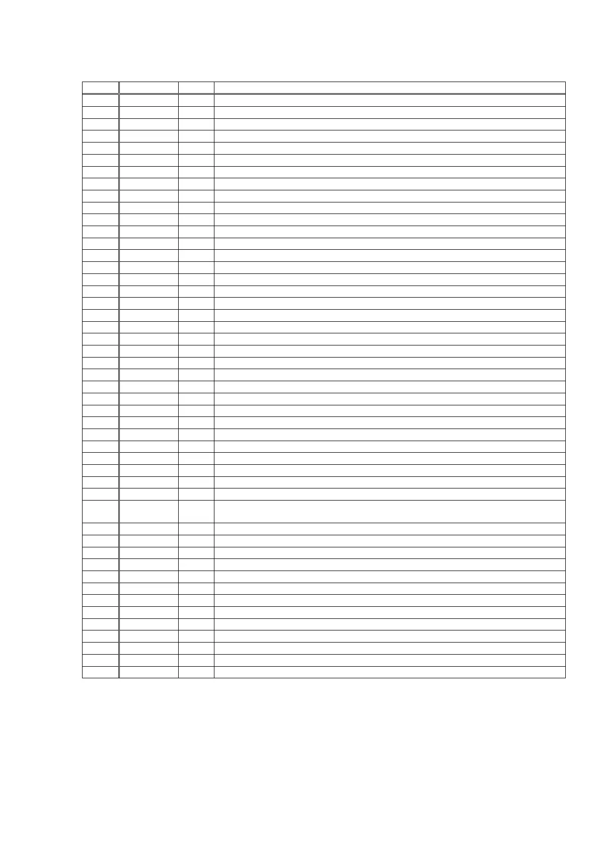
Table 5.1 Pin Functions
Pin No. Name I/O Function
1 RXOUT O
Output pin of Input bi-phase selection data
2 RX0 I
5
Input pin of TTL-compatible digital data
3 RX1 I
Digital data input pin with built-in amplifier that supports coaxial
4 RX2 I
5
Input pin of TTL-compatible digital data
5 RX3 I
5
Input pin of TTL-compatible digital data
6 DGND
Digital GND
7 DV
DD
Digital power supply
8 RX4 I
5
Input pin of TTL-compatible digital data
9 RX5/VI I
5
TTL-compatible digital data || Validity flag input pin for modulation
10 RX6/UI I
5
TTL-compatible digital data || User data input pin for modulation
11 DV
DD
Digital power supply for PLL
12 DGND
Digital GND for PLL
13 LPF O
PLL loop filter connection pin
14 AV
DD
Analog power supply for PLL
15 AGND
Analog GND for PLL
16 RMCK O
R system clock output pin (256fs, 512fs, XIN, VCO)
17 RBCK O/I
R bit clock input/output pin (64fs)
18 DGND
Digital GND
19 DV
DD
Digital power supply
20 RLRCK O/I
R LR clock input/output pin (fs)
21 RDATA O
Output pin of serial audio data
22 SBCK O
S bit clock output pin (32fs, 64fs, 128fs)
23 SLRCK O
S LR clock output pin (fs/2, fs, 2fs)
24 SDIN I
5
Input pin of serial audio data
25 DGND
Digital GND
26 DV
DD
Digital power supply
27 XMCK O
Oscillation amplifier output pin
28 XOUT O
Quartz resonator connection output pin
29 XIN I
Quartz resonator connection, input pin of external supply clock (24.576 MHz or 12.288 MHz)
30 DV
DD
Digital power supply
31 DGND
Digital GND
32 EMPHA/UO I/O
Emphasis information || U data output || Chip address setting pin
33
______
AUDIO/VO I/O
Non-PCM detection || V flag output || Chip address setting pin
34
_____
CKST I/O
Output of clock switch transitional period signal || Demodulation master or slave function switch pin
35
___
INT I/O
Interrupt output for Microcontroller (Possible to select an interrupt factor.) || Modulation or general-purpose
I/O switch pin
36 RERR O
PLL clock error, data error flag output
37 DO O
Microcontroller I/F, read data output pin (3-state)
38 DI I
5
Microcontroller I/F, write data input pin
39 CE I
5
Microcontroller I/F, chip enable input pin
40 CL I
5
Microcontroller I/F, clock input pin
41 XMODE I
5
System reset input pin
42 DGND
Digital GND
43 DV
DD
Digital power supply
44 TMCK/PIO0 I/O
256fs system clock input for modulation || General-purpose I/O input/output pin
45 TMCK/PIO1 I/O
64fs bit clock input for modulation || General-purpose I/O input/output pin
46 TLRCK/PIO2 I/O
fs clock input for modulation || General-purpose I/O input/output pin
47 TLRCK/PIO3 I/O
serial audio data input for modulation || General-purpose I/O input/output pin
48 TXO/PIOEN O/I
Modulation data output || General-purpose I/O enable input pin
1) Withstand voltage input/output: I or O =−0.3 to 3.6V, I
5
=−0.3 to 5.5V
2) Pins 32 and 33 are input pins for chip address setting, when pin 41 = "L".
3) Pin 34 is a demodulation function master or an input pin for slave setting, when pin 41 = "L".
4) Pin 35 is a modulation function or an input pin for general-purpose I/O function switch setting, when pin 41 = "L".
5) ON/OFF for all power supplies must be done at the same timing as a latch-up countermeasure.
QR01 : LC89057W-VF4-E