Technical Notice V1.0 / 01.09 Page 73 / 100
Model CSW 2000/2400 11
11.2 Handling
The unit must be transported flat and must not sustain any shocks.
11.3 Installation
The unit is normally installed close to the machine being cooled, as indicated on these installation plans.
During the installation, allow for a free space of about 0.5m around the refrigeration unit. This distance
must be 1m in front of the exhaust fan. With these precautions, both ventilation and maintenance access
will be made easier.
11.3.1 Hydraulic connections
Except where specifications state otherwise, the connections between the refrigeration unit and the ma-
chine being cooled can be made with pipes with a cross-section diameter at least equal to that indicated
in the technical characteristics.
See section “9.1.2 Technical specifications” on page 71.
11.3.2 Electrical connections
ELECTROCUTION
The machine cabinet must be disconnected from power while connecting the cables.
Power cable .............................................installed with a 3m length (or according to customer specifica-
tions)
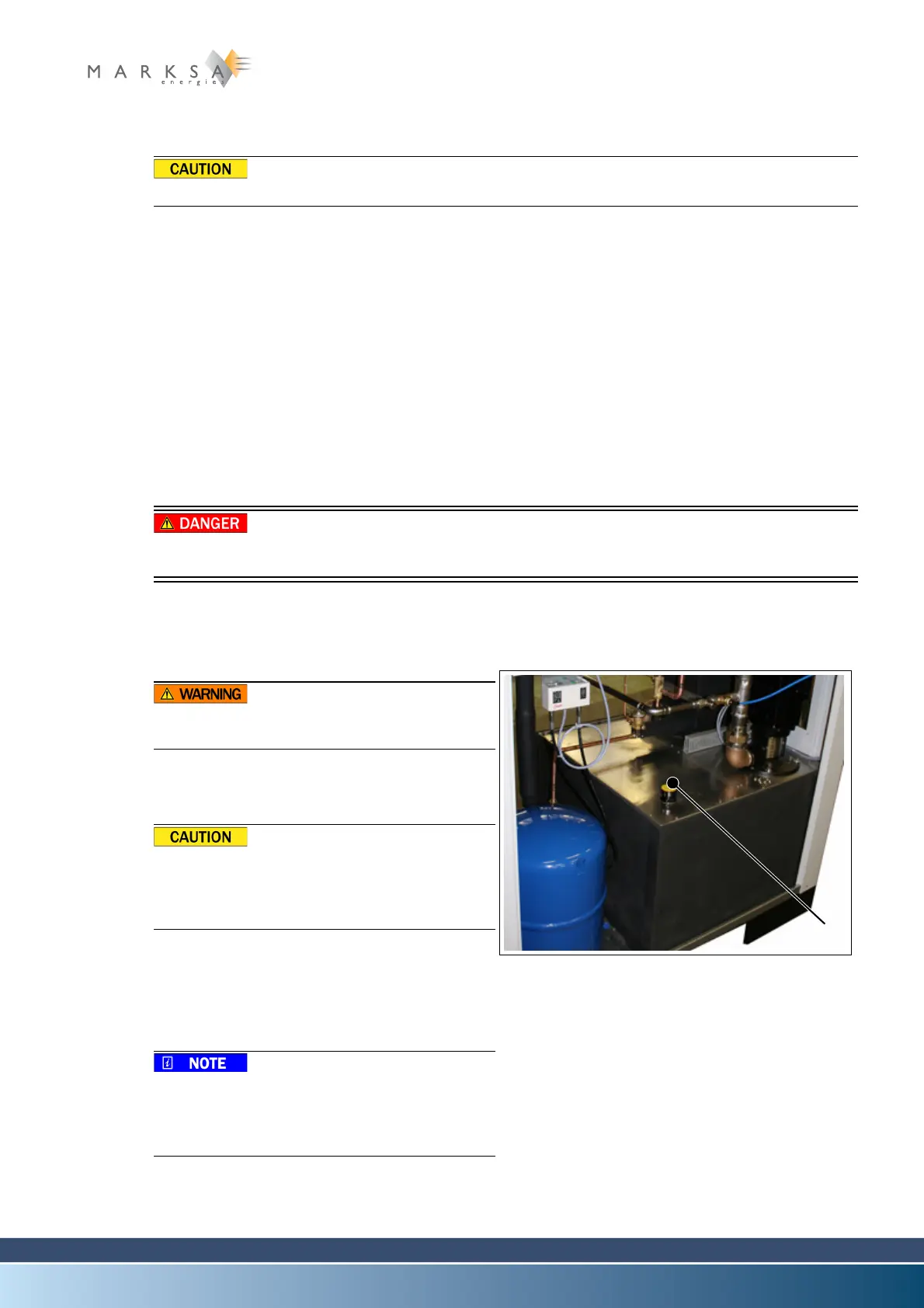
11.3.3 Filling the reservoir
The liquids used are not suitable for human
consumption.
A. Prepare a mixture of water and 30% ethylene gly-
col.
Do not use anti-freeze intended for motor vehi-
cles.
Marksa recommends ANTIFROGEN N antifree-
ze.
B. Unscrew the cap (1).
C. Fill the reservoir to somewhere between the mini-
mum and maximum levels of the indicator (2).
D. Screw the cap back on.
A certain volume of the fluid is used to fill the
machine's circuit. Pay attention to the level
when starting up the machine and top up as
necessary.