Instruction Manual
30
– Instruction Manual
The outputs are not protected. Install a protection device capable of limiting the current at each
output to less than 100 mA in the event of a fault.
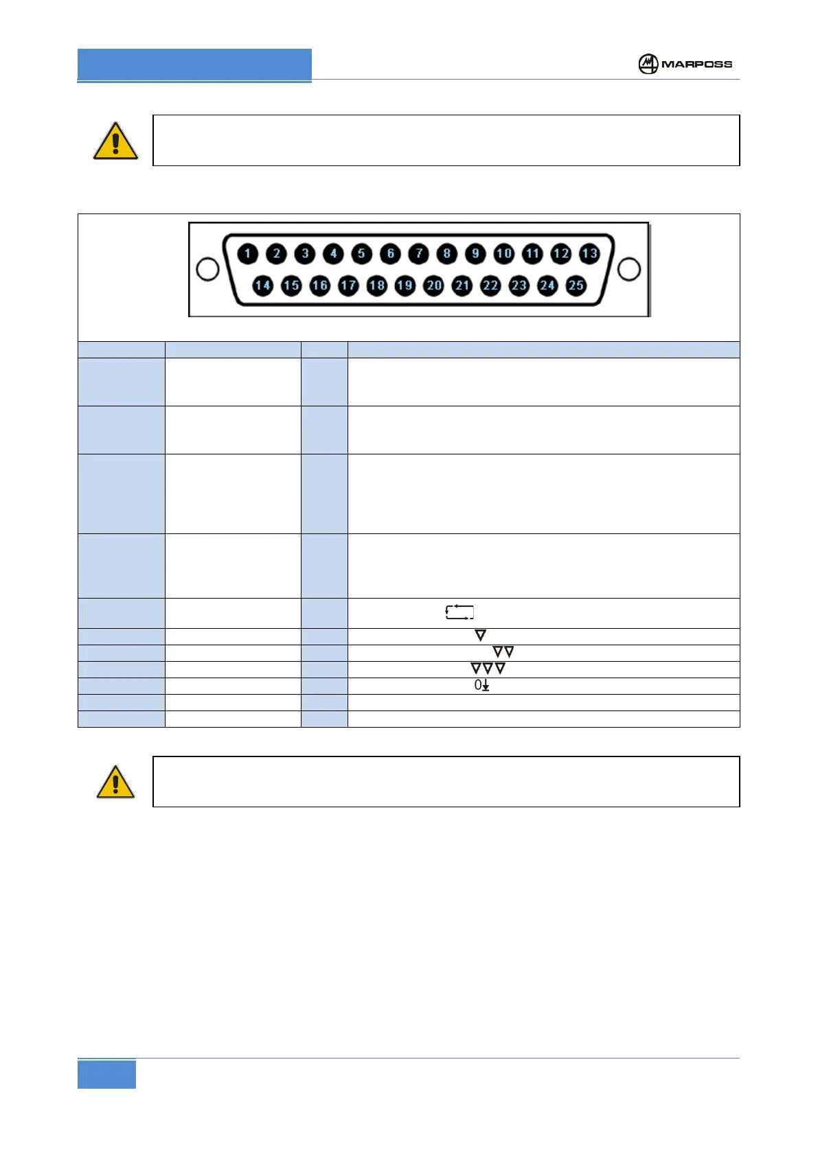
SUBD, 25 pin male machine I/O connector pinout (positioned on rear panel of P1)
SUBD 25 pin male connector
13
Inputs common
The input circuits drive voltage supply must be applied
between this terminal (inputs common
) and each individual
terminal in use (via a micro-switch or similar device).
12
Start cycle IN
The Start Cycle signal is connected to this terminal Remove
the power supply to this terminal to enable measurement
system during working cycle.
9
Outputs common OUT
The output signals can be monitored by connecting the
external loads (relays or other compatible input devices)
between one pole of the power supply to the I/O and each
individual terminal in use. The other pole of the power supply
to the I/O must be connected to this terminal.
7
End delay OUT
The “End delay period (τ)” signal is connected to this terminal.
This signal may be used to enable a solenoid valve in order to
reload the measurement head pneumatic circuit.
6
Automatic OUT
The Automatic signal is connected to this terminal.
The third command signal is connected to this terminal.
The second command signal is connected to this terminal.
The first command signal is connected to this terminal.
The zero command signal is connected to this terminal.
ATTENTION
The length of the I/O (including any branches) connected to the P1 must not exceed 30 m.