FIGURES AND TABLES
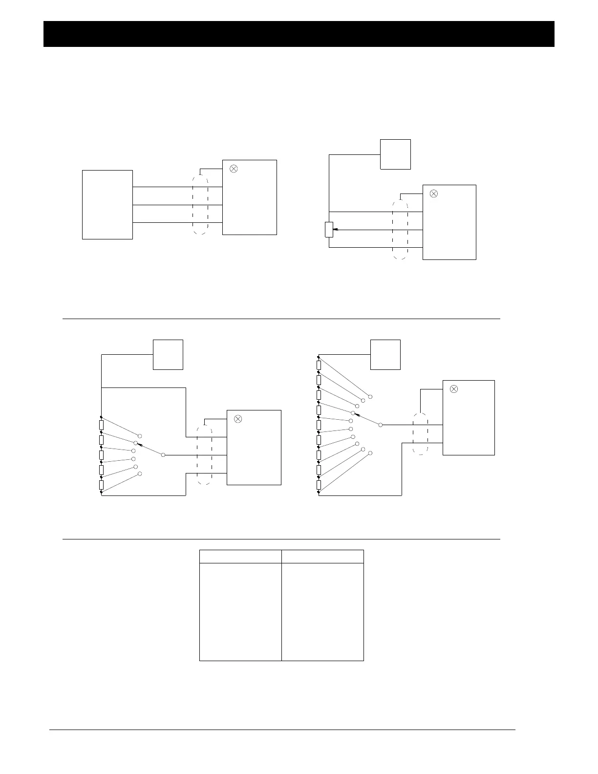
Figure 6. Wiring diagrams, remote tension setpoint
Figure 7. Wiring diagrams, remote setup select
Table 2. Voltage table, remote setup select
Ground
Desired
Tension
Setup
Select
Shield
200
+10 vdc
(External Power Supply)
Ground
Shield
TB4-1, TB4-2,
TB5-1 or TB5-3
TB4-3, TB4-6,
TB5-2 or TB5-4
Setup
Select
Setup 1
Setup 10
Ground
200
Setup
Select
Setup 1
+5 vdc
(External Power Supply)
Setup 6
Shield
Power
Supply
Power
Supply
+5 vdc
(Tension Sensor P+)
OR
Desired
Tension
Shield
TB6-4
(+5 vdc)
Ground
+5 vdc
(Tension
Sensor P+)
1K
200
200
200
200
200
200
200
200
200
200
200
200
+10 vdc
(External Power Supply)
Power
Supply
OR
Analog
Ground
Analog Output
0 to +10 vdc
Analog Output
0 to +10 vdc
TB4-3, TB4-6,
TB5-2 or TB5-4
TB4-1, TB4-2,
TB5-1 or TB5-3
TB5-1 or TB5-3
TB4-1, TB4-2,
VOLTAGE TABLE FOR REMOTE SETUP SELECT
Table 2
TB4-1, TB4-2,
TB5-1 or TB5-3
TB4-3, TB4-6,
TB5-2 or TB5-4
TB4-3, TB4-6,
TB5-2 or TB5-4
TB4-1, TB4-2,
TB5-1 or TB5-3
TB6-4
(+5 vdc)
Figure 6
WIRING DIAGRAMS FOR REMOTE TENSION SETPOINT
Figure 7
WIRING DIAGRAMS FOR REMOTE SETUP SELECT
0+0.25
1±0.25
2±0.25
3±0.25
4±0.25
5±0.25
6±0.25
7±0.25
8±0.25
9±0.25
6
10
9
8
7
5
4
3
2
1
Setup NumberInput Voltage
57

 Loading...


