TESTING
Maytag Chopper Dishwashers
n
3-3
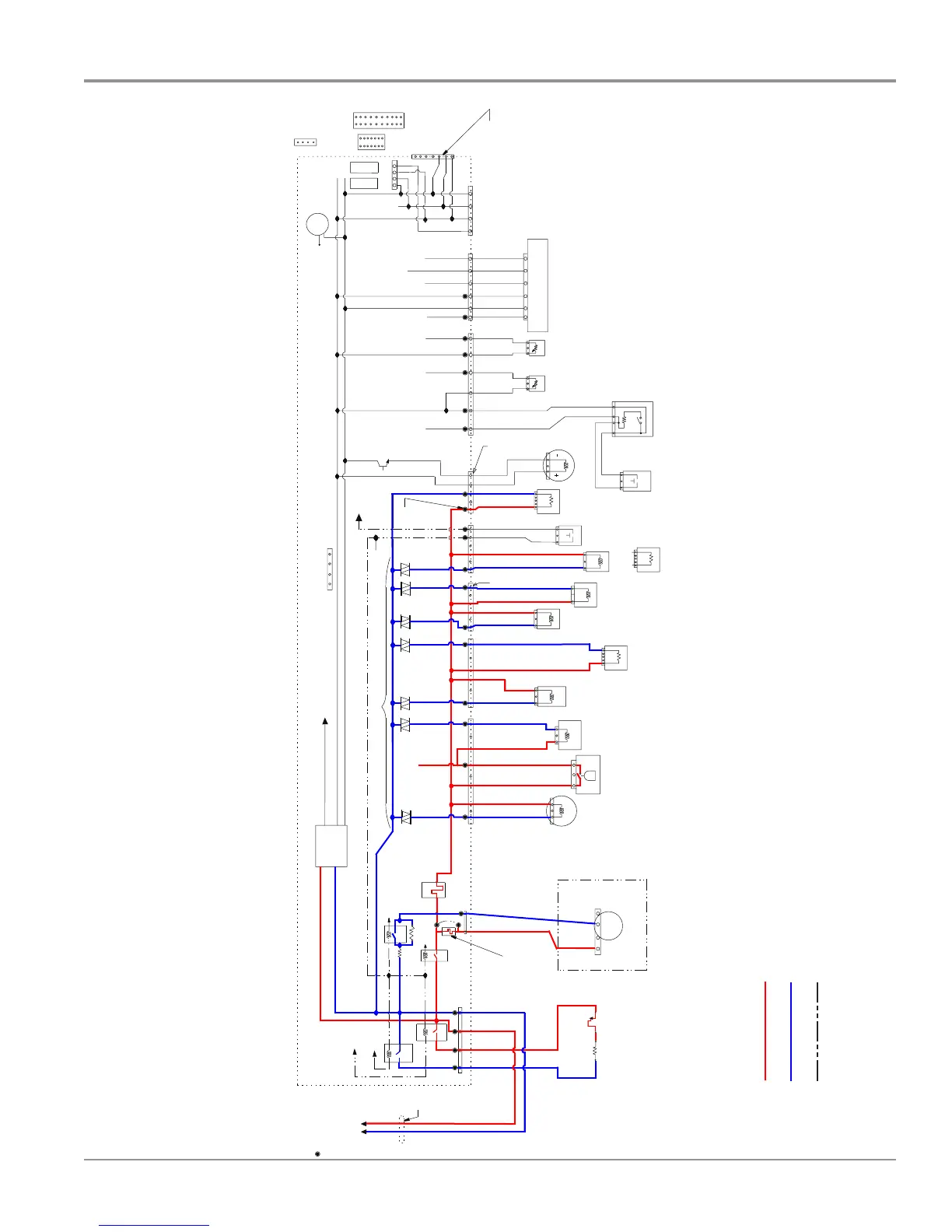
Wiring Diagram
Schemac shown with door switch and all other normally open contacts open.
* Denotes energy ecient components. Do not substute.
For Service Technician Use Only
L1
N
13V
2
Wiring Diagram
Schematic shown with door switch and all other normallyopen contacts open.
*Denotes energyefficient components. Do not substitute.
Line
WH
BK
BK
Line
WH
K1
K3
P4
N
321
1
3
3
3
3
1
1
1
3
1
3
1
3
1
3
1
31
3
12
1
3
12
34
3
1
3
12
4
5
6
123
4
13V
1
3
2
4
5
6
7
Micro Pin
4
3
1
3
1
5
1
Most used test points on
PC board for multimeter
checks
Electronic Control* CCU1 PC Board
7
¹⁄₂
" x 3
³⁄₁₆
" (190.28 mm x 81.01 mm)
2-sided FR4
Micro Pin
Micro Pin
N
HTR-N
Relay
HTR-L
Relay
Ferrite
(1 Loop)
BU/WH
P4-4
P4-3BU/RD
BK
P4-2
WH
P4-1
Thermostat
(Hi-Limit)
BU/R
BU/R
N.C.
Heater
Element
A-Sync Wash
Motor Pump
with Chopper
L1
L1
This option
no fuse,
jumper only
P5-2
LBU
LBU
P5-1
K2
Pilot
Relay
Fuse
F8
P5
W2
Fuse
F9
Micro Pin
Optional
Sense
K4 Motor Relay
Motor Sense Circuit
is different for high
versus low power motors
Return Line 13-volt relays coils goes through door switch
Power Supply
Level 1-3 W
Level 2-4.4 W
Level 3-7.4 W
13V
(+8V)
VCC
(N)
REF
(-5V)
Load (Current) Sense for Drain, Vent, and all other Tr iac loads on Pilot
AC Input
Overfill/Leak Detection
(and Pilot Relay Detection)
P6
P6-1BR
BR P6-3
P6-4
BR
BR
BRBR
P6-6
BR P6-7
BR P6-9
Drain
Motor
Overfill
(Float)
Switch
Fill Valve*
Softener
Regen Valve
(not all models)
TurboZone
Wax Motor
(not all models)
(Spare)
Future
Dispenser
Solenoid
OR
Dispenser
Wax Motor
(Spare)
Future
Door
Switch
Vent Wax Motor
(not all models)
Fan Motor
(not all models)
Flow Meter
Optional
(not many models)
39K
Softener
Salt Sensor
(Closed when empty)
(not all models)
(Spare)
Future
(Spare)
Future
O.W.I.*
(NTC, Foam, and Turbidity Sensor)
Black strip on connector
Red strip on connector
P7-1BU
BU
P7-3
P7-4
BU
BU
P7-6
P8-1
RD
RD
RD
RD
P8-3
P8-4
P8-6
V
V
V
V P9-1
P9-3
P9-5
P9-6
BR
BR
BR
BR
P10-1
P10-3
P10-4
P10-5
RD
RD
RD
RD
RD
RD
P11-1
P11-2
P11-3
P11-4
P11-5
P11-6
YL
YL
YL
YL
YL
YL
P12-1
P12-2
P12-3
P12-4
P12-5
P12-6
P7
P8
P9
P10
P11 P12 P13
Door Open Detection
13V
Pilot L1
Test Pad
for all
Triac
Loads
Fan Load
(Current)
Sense
Analog
Input
Analog
Input
Digital
Input
NTC
Input
Opt
Sig
Foam
Drive
Turbo
Drive
13V
VCC
Wide
Data
REF
Wide Data
VCC
P3
(Wide Out)
Temporary connection
port for development tools
(and future service tools)
P1A and P1B User Interface
Connector Options
Mechanical Push-Button
Boards and Active Overlays
20-Pin
LED
Displa
ys
14-Pin
P1A
P1B
Capacitive
Touch
Keyboards
4-Pin
P1-VCC
P4-REF
Beeper
P2
In-Factory Programming Port
(on top surface of PCB)
(depopulate in production; use pads)
P1C
1
2
3
4
 Loading...